Cisco 877W Hardware Installation Guide - Page 65
Connecting the AC Adapter
 |
UPC - 882658019579
View all Cisco 877W manuals
Add to My Manuals
Save this manual to your list of manuals |
Page 65 highlights
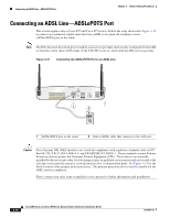
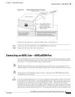
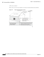
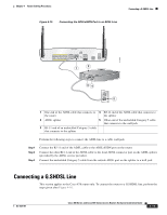
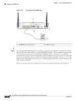
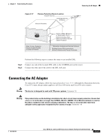
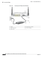
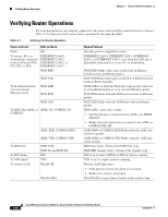
Chapter 4 Router Cabling Procedures Figure 4-17 Primary Protection Device Location Telecom Service Overhead Service Entrance Home or Business Connecting the AC Adapter Router Note: Primary Protection may be located Outside or Inside of Premise Service Utilities Entrance or Demarcation Point Network Interface Box/ Network Interface Device/ Station Protector * Alternative Underground Service Entrance Building Ground Rod connected to Service entrance and Primary Protection 281392 Perform the following steps to connect the router to an installed DSL: Step 1 Connect one end of the lavender DSL cable to the G.SHDSL port on the router. Step 2 Connect the other end of the cable to the DSL wall jack. Connecting the AC Adapter To connect the AC adapter, follow the steps given after Figure 4-18. Although the illustration shows the Cisco 871 router, the procedure applies to all Cisco 850 series and Cisco 870 series routers. Warning The device is designed to work with TN power systems. Statement 19 Warning This product relies on the building's installation for short-circuit (overcurrent) protection. Ensure that a fuse or circuit breaker no larger than 120VAC, 20A U.S. (240VAC, 16 to 20A international) is used on the phase conductors (all current-carrying conductors). The fuse or circuit breaker must have adequate safety approvals recognized by the country of usage. Statement 119 OL-5331-01 Cisco 850 Series and Cisco 870 Series Access Routers Hardware Installation Guide 4-21
-
 1
1 -
2
-
3
-
4
-
5
-
6
-
7
-
8
-
9
-
10
-
11
-
12
-
13
-
14
-
15
-
16
-
17
-
18
-
19
-
20
-
21
-
22
-
23
-
24
-
25
-
26
-
27
-
28
-
29
-
30
-
31
-
32
-
33
-
34
-
35
-
36
-
37
-
38
-
39
-
40
-
41
-
42
-
43
-
44
-
45
-
46
-
47
-
48
-
49
-
50
-
51
-
52
-
53
-
54
-
55
-
56
-
57
-
58
-
59
-
 60
60 -
 61
61 -
 62
62 -
 63
63 -
 64
64 -
 65
65 -
 66
66 -
 67
67 -
 68
68 -
 69
69 -
 70
70 -
71
-
72
-
73
-
74
-
75
-
76
-
77
-
78
-
79
-
80
-
81
-
82
-
83
-
84
-
85
-
86
-
87
-
88
-
89
-
90
-
91
-
92
 |
 |
