Cisco 877W Hardware Installation Guide - Page 60
Connecting an ADSL Line-ADSLoPOTS Port - 877 configuration
 |
UPC - 882658019579
View all Cisco 877W manuals
Add to My Manuals
Save this manual to your list of manuals |
Page 60 highlights
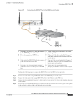
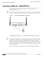
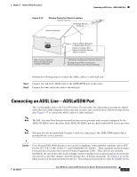
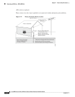
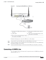
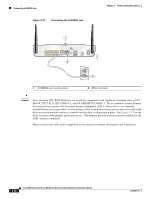
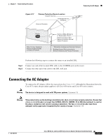
Connecting an ADSL Line-ADSLoPOTS Port Chapter 4 Router Cabling Procedures Connecting an ADSL Line-ADSLoPOTS Port This section applies only to Cisco 857 and Cisco 877 routers. Follow the steps shown after Figure 4-12 to connect an asymmetric digital subscriber line (ADSL) over plain old telephone service (ADSLoPOTS) port on the router. Note The DSL line must have been provisioned by your service provider and correctly configured for the LED to show the carrier detect (CD) status. If the CD LED is not on, check with the DSL service provider. Figure 4-12 Connecting the ADSLoPOTS Port to an ADSL Line LEFT LAN FE0 FE1 FE2 FE3 Cisco 877W ADSLoPOTS RESET CONSOLE AUX +5,+12 VDC 1 2 RIGHT / PRIMARY 117977 1 ADSLoPOTS port on the router 2 End of ADSL cable that connects to the wall jack Caution Cisco Systems DSL WAN Interfaces are tested for compliance with regulatory standards such as FCC Part 68, ITU-T K.21, IEC 61000-4-5, and CSA/EN/IEC/UL 60950-1. These standards assume Primary Protection devices protect the Customer Premise Equipment (CPE). These devices are normally installed by the service provider, local exchange carrier or qualified service person and are located at the telecom service provider entrance, network interface box, or demarcation point. See Figure 4-13 for the likely location of the primary protection device. The primary protection device must be suitable for the xDSL interface employed. Please contact your sales team or qualified service person for further information and installation. 4-16 Cisco 850 Series and Cisco 870 Series Access Routers Hardware Installation Guide OL-5331-01
-
 1
1 -
2
-
3
-
4
-
5
-
6
-
7
-
8
-
9
-
10
-
11
-
12
-
13
-
14
-
15
-
16
-
17
-
18
-
19
-
20
-
21
-
22
-
23
-
24
-
25
-
26
-
27
-
28
-
29
-
30
-
31
-
32
-
33
-
34
-
35
-
36
-
37
-
38
-
39
-
40
-
41
-
42
-
43
-
44
-
45
-
46
-
47
-
48
-
49
-
50
-
51
-
52
-
53
-
54
-
 55
55 -
 56
56 -
 57
57 -
 58
58 -
 59
59 -
 60
60 -
 61
61 -
 62
62 -
 63
63 -
 64
64 -
 65
65 -
66
-
67
-
68
-
69
-
70
-
71
-
72
-
73
-
74
-
75
-
76
-
77
-
78
-
79
-
80
-
81
-
82
-
83
-
84
-
85
-
86
-
87
-
88
-
89
-
90
-
91
-
92
 |
 |
