Cisco 877W Hardware Installation Guide - Page 52
Connecting a Server, PC, or Workstation
 |
UPC - 882658019579
View all Cisco 877W manuals
Add to My Manuals
Save this manual to your list of manuals |
Page 52 highlights
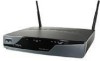
Connecting a Server, PC, or Workstation Chapter 4 Router Cabling Procedures Connecting a Server, PC, or Workstation To connect a server, PC, or workstation to a built-in Ethernet switch port, follow the steps given after Figure 4-6, which shows a Cisco 871 router connected to a PC. The procedure applies to Cisco 850 series and Cisco 870 series routers. Figure 4-6 Connecting a Server, PC, or Workstation 2 1 1 LEFT 0 Cisco 871W LAN WAN FE4 0 FE3 1 FE2 2 FE1 3 FE4 RESET CONSOLE AUX +5,+12 VDC 3 RIGHT / PRIMARY 4 5 117971 1 Router 2 Yellow Ethernet cable 3 Built-in Ethernet switch port on the router 4 PC 5 RJ-45 port on the network interface card (NIC) Cisco 850 Series and Cisco 870 Series Access Routers Hardware Installation Guide 4-8 OL-5331-01
-
 1
1 -
2
-
3
-
4
-
5
-
6
-
7
-
8
-
9
-
10
-
11
-
12
-
13
-
14
-
15
-
16
-
17
-
18
-
19
-
20
-
21
-
22
-
23
-
24
-
25
-
26
-
27
-
28
-
29
-
30
-
31
-
32
-
33
-
34
-
35
-
36
-
37
-
38
-
39
-
40
-
41
-
42
-
43
-
44
-
45
-
46
-
 47
47 -
 48
48 -
 49
49 -
 50
50 -
 51
51 -
 52
52 -
 53
53 -
 54
54 -
 55
55 -
 56
56 -
 57
57 -
58
-
59
-
60
-
61
-
62
-
63
-
64
-
65
-
66
-
67
-
68
-
69
-
70
-
71
-
72
-
73
-
74
-
75
-
76
-
77
-
78
-
79
-
80
-
81
-
82
-
83
-
84
-
85
-
86
-
87
-
88
-
89
-
90
-
91
-
92
 |
 |
