Compaq Evo Notebook PC n115 Compaq Evo N115 Series Maintenance and Service Gui
Compaq Evo Notebook PC n115 Manual
 |
View all Compaq Evo Notebook PC n115 manuals
Add to My Manuals
Save this manual to your list of manuals |
Compaq Evo Notebook PC n115 manual content summary:
- Compaq Evo Notebook PC n115 | Compaq Evo N115 Series Maintenance and Service Gui - Page 1
Guide Compaq Evo N115 Series Document Part Number: 263816-001 January 2002 This guide is a troubleshooting reference used for maintaining and servicing the notebook. It provides comprehensive information on identifying computer features, components, and spare parts, troubleshooting computer problems - Compaq Evo Notebook PC n115 | Compaq Evo N115 Series Maintenance and Service Gui - Page 2
Group, L.P. Compaq, the Compaq logo, and Evo are trademarks of Compaq Information Technologies Compaq products are set forth in the express limited warranty statements accompanying such products. Nothing herein should be construed as constituting an additional warranty. Maintenance and Service Guide - Compaq Evo Notebook PC n115 | Compaq Evo N115 Series Maintenance and Service Gui - Page 3
2.2 Troubleshooting Flowcharts 2-2 3 Illustrated Parts Catalog 3.1 Serial Number Location 3-1 3.2 Computer System Major Components 3-2 3.3 Plastics and Hardware Kit Components 3-8 3.4 Cable Kit Components 3-9 3.5 Mass Storage Devices 3-10 3.6 Miscellaneous 3-12 Maintenance and Service Guide - Compaq Evo Notebook PC n115 | Compaq Evo N115 Series Maintenance and Service Gui - Page 4
4 Removal and Replacement Preliminaries 4.1 Tools Required 4-1 4.2 Service Considerations 4-2 Plastic Parts 4-2 Cables and Connectors 4-2 4.3 Preventing Damage to Removable Drives 4-3 4.4 5-52 5.20 Audio Board 5-54 5.21 Fan 5-56 5.22 System Board 5-58 iv Maintenance and Service Guide - Compaq Evo Notebook PC n115 | Compaq Evo N115 Series Maintenance and Service Gui - Page 5
6 Specifications A Connector Pin Assignments B Power Cord Set Requirements 3-Conductor Power Cord Set B-1 General Requirements B-1 Country-Specific Requirements B-2 Notes B-2 C Screw Listing Index Maintenance and Service Guide v - Compaq Evo Notebook PC n115 | Compaq Evo N115 Series Maintenance and Service Gui - Page 6
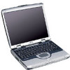
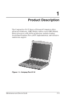
N115 Series of Personal Computers offers advanced modularity, AMD Mobile Athlon 4 and AMD Mobile Duron processors with 64-bit architecture, industry-leading Accelerated Graphics Port (AGP) implementation, and extensive multimedia support. Figure 1-1. Compaq Evo N115 Maintenance and Service Guide - Compaq Evo Notebook PC n115 | Compaq Evo N115 Series Maintenance and Service Gui - Page 7
Compaq Evo N115 Models and Model Naming Conventions Key N1 A 100 X4 20 V M 25 L O XXXXXX-XXX 1 2 3 4 5 6 7 8 9 10 11 Key Description Options 1 Brand/Series designator N1 = Evo Notebook , Lithium ion (Li ion) 10 Operating system O = Windows XP 11 SKU# 1-2 Maintenance and Service Guide - Compaq Evo Notebook PC n115 | Compaq Evo N115 Series Maintenance and Service Gui - Page 8
Product Description Table 1-1 Compaq Evo N115 Models and Model Naming Conventions (Continued) Build-to-Order Models 1 2 3 4 5 6 7 8 9 10 11 N1 A 100 X4 20 W M 25 L 470024-541 Spain Config. code = KDH2 470024-542 Thailand Config. code = KDKV 470024-535 Maintenance and Service Guide 1-3 - Compaq Evo Notebook PC n115 | Compaq Evo N115 Series Maintenance and Service Gui - Page 9
Product Description Table 1-1 Compaq Evo N115 Models and Model Naming Conventions (Continued) Build-to-Order Models (Continued) N1 D 950 X4 20 V M 25 L O SKU# = KDH1 470023-968 India Config. code = KDH1 470023-556 Thailand Config. code = KDH1 470024-534 1-4 Maintenance and Service Guide - Compaq Evo Notebook PC n115 | Compaq Evo N115 Series Maintenance and Service Gui - Page 10
Product Description Table 1-1 Compaq Evo N115 Models and Model Naming Conventions (Continued) Build-to-Order Models (Continued) N1 D 900 X4 20 W M 25 L O SKU# 470020-484 Spain (NAFTA) Config. code = KDH9 470020-489 Sweden Config. code = KDJS 470020-485 Maintenance and Service Guide 1-5 - Compaq Evo Notebook PC n115 | Compaq Evo N115 Series Maintenance and Service Gui - Page 11
Product Description Table 1-1 Compaq Evo N115 Models and Model Naming Conventions (Continued) Build-to-Order Models (Continued) N1 D 900 X4 20 R M 25 L O SKU# Japan C 12 L O 470025-441 N1 D 950 X4 20 D C 25 L O 470025-438 N1 D 950 X4 20 D C 12 L O 470025-436 1-6 Maintenance and Service Guide - Compaq Evo Notebook PC n115 | Compaq Evo N115 Series Maintenance and Service Gui - Page 12
Product Description Table 1-1 Compaq Evo N115 Models and Model Naming Conventions (Continued) Configure-to-Order Models All configure-to-order models are United States D C 12 L O 470025-414 N1 D 950 X3 10 D C 12 L O 470025-415 N1 D 900 X4 15 D C 25 L O 470024-821 Maintenance and Service Guide 1-7 - Compaq Evo Notebook PC n115 | Compaq Evo N115 Series Maintenance and Service Gui - Page 13
pointing device I Network interface card (NIC) integrated on the system board, with a mini PCI V.92 modem I Support for one Type I/II/III PC Card slot with support for both 32-bit CardBus and 16-bit PC Cards I External 60W AC adapter with power cord I 8-cell Lithium ion (Li ion) battery pack I 30 - Compaq Evo Notebook PC n115 | Compaq Evo N115 Series Maintenance and Service Gui - Page 14
keyboard/mouse I JBL Pro stereo speakers with bass reflex 1.3 Clearing a Password If the notebook you are servicing has an unknown password, follow these steps to clear the password. These steps also clear . All passwords and all CMOS settings have been cleared. Maintenance and Service Guide 1-9 - Compaq Evo Notebook PC n115 | Compaq Evo N115 Series Maintenance and Service Gui - Page 15
power management features that extend battery operating time and conserve power. The computer supports the following power management features: I Standby I Hibernation I Setting customization by I Advanced Configuration and Power Management (ACP) compliance 1-10 Maintenance and Service Guide - Compaq Evo Notebook PC n115 | Compaq Evo N115 Series Maintenance and Service Gui - Page 16
microphone. Connects stereo speakers, headphones, headset, or television audio. Accepts a CD-ROM, CD-RW, DVD-ROM, or combination DVD-ROM/CD-RW drive. Maintenance and Service Guide 1-11 - Compaq Evo Notebook PC n115 | Compaq Evo N115 Series Maintenance and Service Gui - Page 17
Product Description The computer left side components are shown in Figure 1-3 and described in Table 1-3. Figure 1-3. Left Side Components 1-12 Maintenance and Service Guide - Compaq Evo Notebook PC n115 | Compaq Evo N115 Series Maintenance and Service Gui - Page 18
the computer on a blanket, rug, or other flexible surface that may cover the vent area. PC Card eject button Ejects a PC Card from the PC Card slot. PC Card slot Supports a 32-bit (CardBus) or 16-bit PC Card. Diskette drive Accepts 3.5-inch diskettes. Maintenance and Service Guide 1-13 - Compaq Evo Notebook PC n115 | Compaq Evo N115 Series Maintenance and Service Gui - Page 19
only available power source has reached a low-battery condition. Turns on when the hard drive, CD-, or DVD-ROM drive is accessed. 1-14 Maintenance and Service Guide - Compaq Evo Notebook PC n115 | Compaq Evo N115 Series Maintenance and Service Gui - Page 20
cable is not included with the computer. Connects the modem cable to an internal modem. A modem cable is included with internal modem models. Maintenance and Service Guide 1-15 - Compaq Evo Notebook PC n115 | Compaq Evo N115 Series Maintenance and Service Gui - Page 21
Product Description The keyboard components are shown in Figure 1-5 and described in Table 1-5. Figure 1-5. Keyboard Components 1-16 Maintenance and Service Guide - Compaq Evo Notebook PC n115 | Compaq Evo N115 Series Maintenance and Service Gui - Page 22
one that is displayed by pressing the right mouse button. Displays the Windows Start menu. Used with hotkeys to perform preset hotkey functions. Maintenance and Service Guide 1-17 - Compaq Evo Notebook PC n115 | Compaq Evo N115 Series Maintenance and Service Gui - Page 23
is on and the embedded numeric keypad is enabled. Turns on when the hard drive, CD-, or DVD-ROM drive is accessed. 1-18 Maintenance and Service Guide - Compaq Evo Notebook PC n115 | Compaq Evo N115 Series Maintenance and Service Gui - Page 24
source has reached a low-battery condition. Provide quick access to the Internet. Refer to the Hardware Guide that ships with the computer for information about these buttons. Turns on the computer. Use the screen left, right, up, and down. Opens the computer. Maintenance and Service Guide 1-19 - Compaq Evo Notebook PC n115 | Compaq Evo N115 Series Maintenance and Service Gui - Page 25
cover the vent area. Memory expansion compartment Covers the memory expansion compartment that contains two memory expansion slots for memory expansion boards. 1-20 Maintenance and Service Guide - Compaq Evo Notebook PC n115 | Compaq Evo N115 Series Maintenance and Service Gui - Page 26
may be needed when you call Compaq customer support or use some Windows operating systems. Secures the hard drive to the computer. Supports the removable primary hard drive. The hard drive is secured to the computer by one screw. Contains the mini PCI modem card. Maintenance and Service Guide 1-21 - Compaq Evo Notebook PC n115 | Compaq Evo N115 Series Maintenance and Service Gui - Page 27
I Display I Keyboard/TouchPad or pointing stick I Audio I AMD Athlon and Duron processors I Fan I PC Card I Modem or modem/NIC The computer uses an electrical fan for ventilation. The fan is controlled cm) clearance on the left and right sides of the computer. 1-22 Maintenance and Service Guide - Compaq Evo Notebook PC n115 | Compaq Evo N115 Series Maintenance and Service Gui - Page 28
authorized technicians trained by Compaq should repair this equipment. All troubleshooting and repair procedures are default settings and configure the system BIOS to diagnose and solve minor problems. I Power Management-Allows you to reduce your computer power consumption. and Service Guide 2-1 - Compaq Evo Notebook PC n115 | Compaq Evo N115 Series Maintenance and Service Gui - Page 29
2.7 2.8 2.9 2.10 2.11 2.12 2.13 2.14 2.15 2.16 2.17 2.18 2.19 2.20 Description Initial troubleshooting No power, part 1 No power, part 2 No power, part 3 No power, part 4 No video, part 1 keyboard Nonfunctioning pointing device No network or modem connection 2-2 Maintenance and Service Guide - Compaq Evo Notebook PC n115 | Compaq Evo N115 Series Maintenance and Service Gui - Page 30
Flowchart 2.1 - Initial Troubleshooting Begin troubleshooting. N Is there power? Y Go to Section 2.2, No Power. N Beeps, LEDs, or error messages? Y Check LED board, Section 2.19, Nonfunctioning Pointing Device. Go to Section 2.20, No Network or Modem. End Maintenance and Service Guide 2-3 - Compaq Evo Notebook PC n115 | Compaq Evo N115 Series Maintenance and Service Gui - Page 31
Troubleshooting Flowchart 2.2 - No Power, Part 1 No Power (power LED is off). Remove from docking station (if applicable). N Power up on battery power? switch and either the lid switch or the main power switch. Go to Section 2.8, Nonfunctioning Docking Station. 2-4 Maintenance and Service Guide - Compaq Evo Notebook PC n115 | Compaq Evo N115 Series Maintenance and Service Gui - Page 32
Troubleshooting Flowchart 2.3 - No Power, Part 2 Continued from Section 2.2, No Power, Part 1. Visually check for debris in battery socket and clean on? Y Replace power supply (if applicable). N Done Power on? Y Go to Section 2.4, No Power, Part 3. Done Maintenance and Service Guide 2-5 - Compaq Evo Notebook PC n115 | Compaq Evo N115 Series Maintenance and Service Gui - Page 33
Troubleshooting Flowchart 2.4 - No Power, Part 3 Continued from Section 2.3, No Power, Part 2. Plug directly into AC outlet. Y Power LED on? N AC adapter? Replace external AC adapter. Internal Go to Section 2.5, No Power, Part 4. N Power on? Y Done Done 2-6 Maintenance and Service Guide - Compaq Evo Notebook PC n115 | Compaq Evo N115 Series Maintenance and Service Gui - Page 34
2.5 - No Power, Part 4 Continued from Section 2.4, No Power, Part 3. Troubleshooting Open computer. Y Loose or damaged parts? N Reseat loose components and boards and replace System board* *Replace these items as a set to prevent shorting out among components. Maintenance and Service Guide 2-7 - Compaq Evo Notebook PC n115 | Compaq Evo N115 Series Maintenance and Service Gui - Page 35
Troubleshooting Flowchart 2.6 - No Video, Part 1 No Video. Stand-alone or Docking Station pins on cable. Replace the following one at a time. Test after each replacement. 1. Cable between notebook and computer display (if applicable) 2. Inverter board (if applicable) 3. Display 4. System board N - Compaq Evo Notebook PC n115 | Compaq Evo N115 Series Maintenance and Service Gui - Page 36
Troubleshooting Flowchart 2.7 - No Video, Part 2 Continued from Section 2.6, No Video, Part 1. Remove notebook from docking station, if connected. Adjust display brightness. Check brightness of external Section 2.8, Nonfunctioning Docking Station. Done Done Maintenance and Service Guide 2-9 - Compaq Evo Notebook PC n115 | Compaq Evo N115 Series Maintenance and Service Gui - Page 37
Troubleshooting notebook into docking station. Y Docking station operating? N Done Replace the following docking station components one at a time. Check computer operation after each replacement. 1. Power supply 2. I/O board 3. Backplane board 4. Switch box 2-10 Maintenance and Service Guide - Compaq Evo Notebook PC n115 | Compaq Evo N115 Series Maintenance and Service Gui - Page 38
Troubleshooting Flowchart 2.9 - No Operating System (OS) Loading No OS Loading.* Reseat power 2.14. No OS loading from network, go to Section 2.20. *Before beginning troubleshooting, always check cable connections, cable ends, and drives for bent or damaged pins. Maintenance and Service Guide 2-11 - Compaq Evo Notebook PC n115 | Compaq Evo N115 Series Maintenance and Service Gui - Page 39
Troubleshooting Flowchart 2.10 - No OS Loading from Hard Drive, Part 1 OS not loading from hard drive. Y Nonsystem disk message? N Go to boot priority through the setup utility and reboot. N Boot from hard drive? Y Go to Section 2.17, Nonfunctioning Device. 2-12 Maintenance and Service Guide - Compaq Evo Notebook PC n115 | Compaq Evo N115 Series Maintenance and Service Gui - Page 40
Troubleshooting Flowchart 2.11 - No OS Loading from Hard Drive, Part 2 Continued from Section 2.10, No OS Loading from Hard Drive, Part 1. N Computer booted? N Go to Section 2.12, No OS Loading from Hard Drive, Part 3. Load OS using Restore CD (if applicable). Maintenance and Service Guide 2-13 - Compaq Evo Notebook PC n115 | Compaq Evo N115 Series Maintenance and Service Gui - Page 41
Troubleshooting Flowchart 2.12 - No OS Loading from Hard Drive, Part 3 Continued from Section 2.11, No OS Loading from Hard Drive, Part 2. N recommendations. N Fix bad sectors. Boot from hard drive? Replace hard drive. Y Done Replace hard drive. Done 2-14 Maintenance and Service Guide - Compaq Evo Notebook PC n115 | Compaq Evo N115 Series Maintenance and Service Gui - Page 42
Troubleshooting Flowchart 2.13 - No OS Loading from Diskette . Clear CMOS. Refer to Section 1.2, "Clearing a Password," for instructions. N Bootable diskette in drive? Install bootable diskette and reboot computer. Go to Section 2.17, Nonfunctioning Device. Maintenance and Service Guide 2-15 - Compaq Evo Notebook PC n115 | Compaq Evo N115 Series Maintenance and Service Gui - Page 43
Troubleshooting Flowchart 2.14 - No OS Loading from CD- or DVD-ROM Drive Y N to Section 2.17, Nonfunctioning Device. Clear CMOS. Refer to Section 1.2, "Clearing a Password," for instructions. Correct boot order using the setup utility. Go to Section 2.17, Nonfunctioning Device. 2-16 - Compaq Evo Notebook PC n115 | Compaq Evo N115 Series Maintenance and Service Gui - Page 44
Troubleshooting Flowchart 2.15 - No Audio, Part 1 Y No Audio. Turn up audio internally or externally. Audio? Done N Y Notebook in docking station (if applicable)? N Undock N Internal audio? Go Go to Section 2.17, Nonfunctioning Device. Y Audio? N Done Maintenance and Service Guide 2-17 - Compaq Evo Notebook PC n115 | Compaq Evo N115 Series Maintenance and Service Gui - Page 45
Troubleshooting Flowchart 2.16 - No Audio, Part 2 Continued from Section 2.15, No Audio, Part 1. N Audio in OS. Connect to external speaker. N Audio? Y Replace audio board and speaker connections in notebook (if applicable). Y Audio? N 1. Replace internal speakers. 2. Replace audio board (if - Compaq Evo Notebook PC n115 | Compaq Evo N115 Series Maintenance and Service Gui - Page 46
Flowchart 2.17 - Nonfunctioning Device Nonfunctioning Device. Troubleshooting Reseat device. Clear CMOS. Unplug the nonfunctioning device from the notebook, inspect cables and plugs for bent or ? Y Done Possible bad diskette drive. Replace drive. Done Maintenance and Service Guide 2-19 - Compaq Evo Notebook PC n115 | Compaq Evo N115 Series Maintenance and Service Gui - Page 47
operating properly. Connect notebook to good external keyboard. N External device works? Y Replace system board. Reseat internal keyboard connector (if applicable). N OK? Y Replace internal keyboard or cable. Y Done OK? N Replace system board. Done 2-20 Maintenance and Service Guide - Compaq Evo Notebook PC n115 | Compaq Evo N115 Series Maintenance and Service Gui - Page 48
Connect notebook to good external pointing device. N External device works? Y Replace system board. Reseat internal pointing device connector (if applicable). N OK? Y Replace internal pointing device or cable. Y Done OK? N Replace system board. Done Maintenance and Service Guide 2-21 - Compaq Evo Notebook PC n115 | Compaq Evo N115 Series Maintenance and Service Gui - Page 49
Troubleshooting Flowchart 2.20 - Network or Modem Connection No network or modem connection. N modem configured in OS? Reload drivers and reconfigure. Y N Y OK? Disconnect all power from the notebook and open. Reseat NIC/modem (if applicable). Replace NIC/modem (if applicable). Y OK? N Done - Compaq Evo Notebook PC n115 | Compaq Evo N115 Series Maintenance and Service Gui - Page 50
or requesting information, provide the computer serial number and model number located on the bottom of the computer (Figure 3-1). Figure 3-1. Serial Number Location Maintenance and Service Guide 3-1 - Compaq Evo Notebook PC n115 | Compaq Evo N115 Series Maintenance and Service Gui - Page 51
Illustrated Parts Catalog 3.2 Computer System Major Components Figure 3-2. Computer System Major Components 3-2 Maintenance and Service Guide - Compaq Evo Notebook PC n115 | Compaq Evo N115 Series Maintenance and Service Gui - Page 52
-001 254114-162 254114-091 254114-241 254114-131 254114-072 254114-101 254114-111 254114-AB1 254114-281 254114-031 254114-001 Maintenance and Service Guide 3-3 - Compaq Evo Notebook PC n115 | Compaq Evo N115 Series Maintenance and Service Gui - Page 53
Illustrated Parts Catalog Computer System Major Components (continued) 3-4 Maintenance and Service Guide - Compaq Evo Notebook PC n115 | Compaq Evo N115 Series Maintenance and Service Gui - Page 54
and 264298-001 279769-001 254116-001 254105-001 239184-001 239182-001 260738-001 249664-001 239181-001 265994-001 254120-001 Maintenance and Service Guide 3-5 - Compaq Evo Notebook PC n115 | Compaq Evo N115 Series Maintenance and Service Gui - Page 55
Illustrated Parts Catalog Computer System Major Components (continued) 3-6 Maintenance and Service Guide - Compaq Evo Notebook PC n115 | Compaq Evo N115 Series Maintenance and Service Gui - Page 56
-001 254109-001 248776-001 248777-002 273487-001 254103-001 254118-001 254115-001 216173-001 200349-001 247051-001 247050-001 Maintenance and Service Guide 3-7 - Compaq Evo Notebook PC n115 | Compaq Evo N115 Series Maintenance and Service Gui - Page 57
rail Hard drive bezel Item 6 7 8 Description Mini PCI slot cover Left side panel Right side panel 9 Battery bracket 10 Memory expansion slot cover 3-8 Maintenance and Service Guide - Compaq Evo Notebook PC n115 | Compaq Evo N115 Series Maintenance and Service Gui - Page 58
Illustrated Parts Catalog 3.4 Cable Kit Components Figure 3-4. Cable Kit Components Table 3-3 Cable Kit Components Spare Part Number 254120-001 Item 1 2 Description Diskette drive cable Audio board cable Maintenance and Service Guide 3-9 - Compaq Evo Notebook PC n115 | Compaq Evo N115 Series Maintenance and Service Gui - Page 59
Illustrated Parts Catalog 3.5 Mass Storage Devices Figure 3-5. Mass Storage Devices l Table 3-4 Mass Storage Devices Item 1 Description Hard drives 30 GB 20 GB 15 GB 10 GB Spare Part Number 192406-001 200350-001 216173-001 200349-001 3-10 Maintenance and Service Guide - Compaq Evo Notebook PC n115 | Compaq Evo N115 Series Maintenance and Service Gui - Page 60
drive DVD-ROM/CD-RW combination drive Spare Part Number 254119-001 254110-001 254111-001 254112-001 254113-001 and 264298-001 Maintenance and Service Guide 3-11 - Compaq Evo Notebook PC n115 | Compaq Evo N115 Series Maintenance and Service Gui - Page 61
-291 Swiss U.K. English North America 170513-115 170513-031 293831-001 Memory expansion boards 256 MB 128 MB 244399-001 239190-001 3-12 Maintenance and Service Guide - Compaq Evo Notebook PC n115 | Compaq Evo N115 Series Maintenance and Service Gui - Page 62
Preliminaries This chapter provides essential information for proper and safe removal and replacement service. 4.1 Tools Required You will need the following tools to complete the removal kit (includes connector removal tool, loopback plugs, and case utility tool) Maintenance and Service Guide 4-1 - Compaq Evo Notebook PC n115 | Compaq Evo N115 Series Maintenance and Service Gui - Page 63
4.2 Service Considerations The Apply pressure only at the points designated in the maintenance instructions. Cables and Connectors Cables must be handled with extreme care extreme care; these cables tear easily. Ä CAUTION: When servicing the computer, ensure that cables are placed in their - Compaq Evo Notebook PC n115 | Compaq Evo N115 Series Maintenance and Service Gui - Page 64
mailed, place the drive in a bubble pack mailer or other suitable form of protective packaging and label the package "Fragile: Handle With Care." Maintenance and Service Guide 4-3 - Compaq Evo Notebook PC n115 | Compaq Evo N115 Series Maintenance and Service Gui - Page 65
-free workstations. I Place items on a grounded surface before removing items from their containers. I Always be properly grounded when touching a sensitive component or assembly. 4-4 Maintenance and Service Guide - Compaq Evo Notebook PC n115 | Compaq Evo N115 Series Maintenance and Service Gui - Page 66
properly grounded work surface and use properly grounded tools and equipment. I Use conductive field service tools, such as cutters, screwdrivers, and vacuums. I When using fixtures that must input signals before inserting or removing connectors or test equipment. Maintenance and Service Guide 4-5 - Compaq Evo Notebook PC n115 | Compaq Evo N115 Series Maintenance and Service Gui - Page 67
I Nonconductive foam I Conductive tabletop workstations with ground cords of one-megohm resistance I Static-dissipative tables or floor mats with hard ties to the ground I Field service kits I Static awareness labels I Material-handling packages 4-6 Maintenance and - Compaq Evo Notebook PC n115 | Compaq Evo N115 Series Maintenance and Service Gui - Page 68
4-2 Static-Shielding Materials Material Antistatic plastic Carbon-loaded plastic Metallized laminate Use Bags Floor mats Floor mats Voltage Protection Level 1,500 V 7,500 V 5,000 V Maintenance and Service Guide 4-7 - Compaq Evo Notebook PC n115 | Compaq Evo N115 Series Maintenance and Service Gui - Page 69
are removed during disassembly. There are 62 screws, standoffs, and screwlocks, in 11 different sizes, that must be removed and replaced when servicing the computer. Make special note of each screw size and location during removal and replacement. Refer to Appendix C, "Screw Listing," for detailed - Compaq Evo Notebook PC n115 | Compaq Evo N115 Series Maintenance and Service Gui - Page 70
Removal and Replacement Procedures 5.1 Serial Number Report the computer serial number to Compaq when requesting information or ordering spare parts. The serial number is located on the bottom of the computer (Figure 5-1). Figure 5-1. Serial Number Location 5-2 Maintenance and Service Guide - Compaq Evo Notebook PC n115 | Compaq Evo N115 Series Maintenance and Service Gui - Page 71
Optical Drive LED cover Keyboard Display Heat spreader # of Screws Removed 0 1 to remove hard drive 4 to separate hard drive from hard drive bracket 0 1 1 2 2 0 7 7 Maintenance and Service Guide 5-3 - Compaq Evo Notebook PC n115 | Compaq Evo N115 Series Maintenance and Service Gui - Page 72
Computer for Disassembly Perform the following steps before disassembling the computer: 1. Turn off the computer. 2. Disconnect the AC adapter and all external devices. 5-4 Maintenance and Service Guide - Compaq Evo Notebook PC n115 | Compaq Evo N115 Series Maintenance and Service Gui - Page 73
release latch 1 toward the back of the computer (Figure 5-2). The left edge of the battery bracket rises up 2. Figure 5-2. Releasing the Battery Pack Maintenance and Service Guide 5-5 - Compaq Evo Notebook PC n115 | Compaq Evo N115 Series Maintenance and Service Gui - Page 74
Removal and Replacement Procedures c. Lift and hold the battery bracket open as far as it will open 1 (Figure 5-3). d. Grasp the edges of the battery pack and slide it to the left to remove it 2. Figure 5-3. Removing the Battery Pack 5-6 Maintenance and Service Guide - Compaq Evo Notebook PC n115 | Compaq Evo N115 Series Maintenance and Service Gui - Page 75
in the Plastics and Hardware Kit (spare part number 254121-001). Reverse the above procedures to install the battery pack and battery bracket. Maintenance and Service Guide 5-7 - Compaq Evo Notebook PC n115 | Compaq Evo N115 Series Maintenance and Service Gui - Page 76
.0 × 7.0 hard drive retention screw 1 (Figure 5-5). c. Slide the hard drive to the right to unseat the hard drive connector 2. Figure 5-5. Releasing the Hard Drive 5-8 Maintenance and Service Guide - Compaq Evo Notebook PC n115 | Compaq Evo N115 Series Maintenance and Service Gui - Page 77
Removal and Replacement Procedures d. Swing the right side of the hard drive up and to the left until it is resting at an angle (Figure 5-6). e. Lift the hard drive straight up and remove it 2. Figure 5-6. Removing the Hard Drive Maintenance and Service Guide 5-9 - Compaq Evo Notebook PC n115 | Compaq Evo N115 Series Maintenance and Service Gui - Page 78
is included in the Plastics and Hardware Kit (spare part number 254121-001). Reverse the above procedure to install the hard drive. 5-10 Maintenance and Service Guide - Compaq Evo Notebook PC n115 | Compaq Evo N115 Series Maintenance and Service Gui - Page 79
Computer Feet 5.5 Memory Expansion Board Memory Expansion Boards Spare Part Number Information Memory expansion boards 256 MB 128 MB 244399-001 239190-001 Maintenance and Service Guide 5-11 - Compaq Evo Notebook PC n115 | Compaq Evo N115 Series Maintenance and Service Gui - Page 80
Memory Expansion Compartment Cover ✎ The memory expansion compartment cover is included in the Plastics and Hardware Kit (spare part number 254121-001). 5-12 Maintenance and Service Guide - Compaq Evo Notebook PC n115 | Compaq Evo N115 Series Maintenance and Service Gui - Page 81
PCI Communication Boards Spare Part Number Information Mini PCI communication boards 56-KBPS domestic modem 56-KBPS international modem 248776-001 248777-002 Maintenance and Service Guide 5-13 - Compaq Evo Notebook PC n115 | Compaq Evo N115 Series Maintenance and Service Gui - Page 82
is included in the Plastics and Hardware Kit (spare part number 254121-001). Figure 5-11. Removing the Mini PCI Communications Slot Cover 5-14 Maintenance and Service Guide - Compaq Evo Notebook PC n115 | Compaq Evo N115 Series Maintenance and Service Gui - Page 83
the connector at a 45-degree angle 2. Figure 5-12. Removing a Mini PCI Communications Board Reverse the above procedure to install a mini PCI communications board. Maintenance and Service Guide 5-15 - Compaq Evo Notebook PC n115 | Compaq Evo N115 Series Maintenance and Service Gui - Page 84
two pewter TM2.0 × 7.5 screws that secure the optical drive to the base enclosure (Figure 5-13). Figure 5-13. Removing the Optical Drive Screws 5-16 Maintenance and Service Guide - Compaq Evo Notebook PC n115 | Compaq Evo N115 Series Maintenance and Service Gui - Page 85
top side up with the front facing forward. 5. Insert a paper clip or similar thin metal rod into the manual release hole on the front bezel of the optical drive 1 (Figure 5-14). Press firmly. 6. Grasp the Reverse the above procedure to install the optical drive. Maintenance and Service Guide 5-17 - Compaq Evo Notebook PC n115 | Compaq Evo N115 Series Maintenance and Service Gui - Page 86
LED Cover Screws 4. Turn the computer top side up with front facing forward. 5. Open the computer as far as it will open. 5-18 Maintenance and Service Guide - Compaq Evo Notebook PC n115 | Compaq Evo N115 Series Maintenance and Service Gui - Page 87
from left to right 3. Figure 5-16. Removing the LED Cover 9. Remove the LED cover. Reverse the above procedure to install the LED cover. Maintenance and Service Guide 5-19 - Compaq Evo Notebook PC n115 | Compaq Evo N115 Series Maintenance and Service Gui - Page 88
-101 254114-111 254114-AB1 254114-281 254114-031 254114-001 1. Prepare the computer for disassembly (Section 5.3). 2. Remove the LED cover (Section 5.8). 5-20 Maintenance and Service Guide - Compaq Evo Notebook PC n115 | Compaq Evo N115 Series Maintenance and Service Gui - Page 89
Removal and Replacement Procedures 3. Swing the back edge of the keyboard up and forward 1 and rest it upside down on the palm rest 2 (Figure 5-17). Figure 5-17. Releasing the Keyboard Maintenance and Service Guide 5-21 - Compaq Evo Notebook PC n115 | Compaq Evo N115 Series Maintenance and Service Gui - Page 90
the keyboard. 5.10 Display Displays Spare Part Number Information Displays 14.1-inch, XGA, CTFT 13.3-inch, XGA, CTFT 254108-001 254107-001 5-22 Maintenance and Service Guide - Compaq Evo Notebook PC n115 | Compaq Evo N115 Series Maintenance and Service Gui - Page 91
. Figure 5-19. Removing the Hinge Cover Screws 6. Position the display so it rests at a 90-degree angle in relationship to the work surface. Maintenance and Service Guide 5-23 - Compaq Evo Notebook PC n115 | Compaq Evo N115 Series Maintenance and Service Gui - Page 92
display hinge covers are included in the Plastics and Hardware Kit (spare part number 254121-001). Figure 5-20. Removing the Hinge Covers 5-24 Maintenance and Service Guide - Compaq Evo Notebook PC n115 | Compaq Evo N115 Series Maintenance and Service Gui - Page 93
Removal and Replacement Procedures 9. Remove the pewter TM2.0 × 7.5 screw 1 that secures the display backlight 2 and display video ground cables 3 to the heat spreader (Figure 5-21). Figure 5-21. Removing the Display Ground Cable Screw Maintenance and Service Guide 5-25 - Compaq Evo Notebook PC n115 | Compaq Evo N115 Series Maintenance and Service Gui - Page 94
3 from the system board and unroute the cable 4 from the heat spreader (Figure 5-22). Figure 5-22. Disconnecting and Unrouting the Display Cables 5-26 Maintenance and Service Guide - Compaq Evo Notebook PC n115 | Compaq Evo N115 Series Maintenance and Service Gui - Page 95
enclosure. Ä CAUTION: Secure the display when removing these screws. The display is secured to the computer only by these screws and will fall if not supported during screw removal. 13. Remove the display 2 (Figure 5-23). Figure 5-23. Removing the Display Maintenance and Service Guide 5-27 - Compaq Evo Notebook PC n115 | Compaq Evo N115 Series Maintenance and Service Gui - Page 96
spreader 254124-001 1. Prepare the computer for disassembly (Section 5.3) and remove the following components: a. LED cover (Section 5.8) b. Keyboard (Section 5.9) c. Display (Section 5.10) 5-28 Maintenance and Service Guide - Compaq Evo Notebook PC n115 | Compaq Evo N115 Series Maintenance and Service Gui - Page 97
four silver TM2.0 × 20.0 spring-loaded screws 2 that secure the heat spreader to the base enclosure. Figure 5-25. Removing the Heat Spreader Screws Maintenance and Service Guide 5-29 - Compaq Evo Notebook PC n115 | Compaq Evo N115 Series Maintenance and Service Gui - Page 98
Removal and Replacement Procedures ✎ The spring-loaded screws should be removed and installed in the 1, 2, 3, 4 sequence stamped into the heat spreader as illustrated in Figure 5-26. Figure 5-26. Heat Spreader Screw Sequence 5-30 Maintenance and Service Guide - Compaq Evo Notebook PC n115 | Compaq Evo N115 Series Maintenance and Service Gui - Page 99
Removal and Replacement Procedures 4. Lift up the front right side of the heat spreader 1 and slide it forward 2 until the back edge of the heat spreader clears the tab 3 on the base enclosure (Figure 5-27). Figure 5-27. Removing the Heat Spreader Maintenance and Service Guide 5-31 - Compaq Evo Notebook PC n115 | Compaq Evo N115 Series Maintenance and Service Gui - Page 100
the palm rest. 8. Disconnect the fan cable 4 from the system board. Figure 5-28. Removing the Heat Spreader (Continued) 9. Remove the heat spreader. 5-32 Maintenance and Service Guide - Compaq Evo Notebook PC n115 | Compaq Evo N115 Series Maintenance and Service Gui - Page 101
for the location of the thermal pad. The Thermal Pad Kit spare part number is 265995-001. Figure 5-29. Replacing the Thermal Pad Maintenance and Service Guide 5-33 - Compaq Evo Notebook PC n115 | Compaq Evo N115 Series Maintenance and Service Gui - Page 102
(Section 5.3) and remove the following components: a. Optical drive device (Section 5.7) b. LED cover (Section 5.8) c. Keyboard (Section 5.9) d. Display (Section 5.10) e. Heat spreader (Section 5.11) 5-34 Maintenance and Service Guide - Compaq Evo Notebook PC n115 | Compaq Evo N115 Series Maintenance and Service Gui - Page 103
unseat the processor from the socket on the system board. 5. Lift the processor straight up and remove it 4. Figure 5-30. Removing the Processor Maintenance and Service Guide 5-35 - Compaq Evo Notebook PC n115 | Compaq Evo N115 Series Maintenance and Service Gui - Page 104
cell RTC battery 279769-001 1. Prepare the computer for disassembly (Section 5.3) and remove the following components: a. Optical drive (Section 5.7) b. LED cover (Section 5.8) 5-36 Maintenance and Service Guide - Compaq Evo Notebook PC n115 | Compaq Evo N115 Series Maintenance and Service Gui - Page 105
(Figure 5-32). Figure 5-32. Removing the Disk Cell RTC Battery ✎ When replacing an RTC battery, insert the battery with the "+" sign facing up. Maintenance and Service Guide 5-37 - Compaq Evo Notebook PC n115 | Compaq Evo N115 Series Maintenance and Service Gui - Page 106
cover (Section 5.8) c. Keyboard (Section 5.9) d. Display (Section 5.10) e. Heat spreader (Section 5.11) 2. Turn the computer bottom side up with the front facing forward. 5-38 Maintenance and Service Guide - Compaq Evo Notebook PC n115 | Compaq Evo N115 Series Maintenance and Service Gui - Page 107
silver TM2.0 × 5.0 screws 2 in the battery bay that secure the top cover to the base enclosure. Figure 5-33. Removing the Top Cover Screws Maintenance and Service Guide 5-39 - Compaq Evo Notebook PC n115 | Compaq Evo N115 Series Maintenance and Service Gui - Page 108
.0 × 7.5 screw 3 that secure the top cover to the base enclosure. Figure 5-34. Disconnecting the TouchPad Cable and Removing the Top Cover Screws 5-40 Maintenance and Service Guide - Compaq Evo Notebook PC n115 | Compaq Evo N115 Series Maintenance and Service Gui - Page 109
base enclosure (Figure 5-35). Figure 5-35. Removing the Top Cover 9. Remove the top cover. Reverse the above procedure to install the top cover. Maintenance and Service Guide 5-41 - Compaq Evo Notebook PC n115 | Compaq Evo N115 Series Maintenance and Service Gui - Page 110
the following components: a. Optical drive (Section 5.7) b. LED cover (Section 5.8) c. Keyboard (Section 5.9) d. Display (Section 5.10) e. Heat spreader (Section 5.11) f. Top cover (Section 5.14) 5-42 Maintenance and Service Guide - Compaq Evo Notebook PC n115 | Compaq Evo N115 Series Maintenance and Service Gui - Page 111
.0 × 5.0 screw 3 that secures the diskette drive to the base enclosure. Figure 5-36. Disconnecting the Diskette Drive Cable and Removing the Diskette Drive Screws Maintenance and Service Guide 5-43 - Compaq Evo Notebook PC n115 | Compaq Evo N115 Series Maintenance and Service Gui - Page 112
Removal and Replacement Procedures 4. Lift up the right side of the diskette drive 1 until the drive rests an angle (Figure 5-37). 5. Slide the diskette drive to the right 2 and remove it from the base enclosure. Figure 5-37. Removing the Diskette Drive 5-44 Maintenance and Service Guide - Compaq Evo Notebook PC n115 | Compaq Evo N115 Series Maintenance and Service Gui - Page 113
Cable Kit (spare part number 254120-001). Figure 5-38. Removing the Diskette Drive Cable Reverse the above procedure to install the diskette drive. Maintenance and Service Guide 5-45 - Compaq Evo Notebook PC n115 | Compaq Evo N115 Series Maintenance and Service Gui - Page 114
drive (Section 5.7) b. LED cover (Section 5.8) c. Keyboard (Section 5.9) d. Display (Section 5.10) e. Heat spreader (Section 5.11) f. Top cover (Section 5.14) g. Diskette drive (Section 5.15) 5-46 Maintenance and Service Guide - Compaq Evo Notebook PC n115 | Compaq Evo N115 Series Maintenance and Service Gui - Page 115
). 3. Lift up on the back edge of the charger board 2 to disconnect it from the system board. Figure 5-39. Disconnecting the Charger Board Maintenance and Service Guide 5-47 - Compaq Evo Notebook PC n115 | Compaq Evo N115 Series Maintenance and Service Gui - Page 116
board. 5.17 Left Side Panel ✎ The left side panel is included in the Plastics and Hardware Kit (spare part number 254121-001). 5-48 Maintenance and Service Guide - Compaq Evo Notebook PC n115 | Compaq Evo N115 Series Maintenance and Service Gui - Page 117
remove it from the base enclosure 3. Figure 5-41. Removing the Left Side Panel Reverse the above procedure to install the left side panel. Maintenance and Service Guide 5-49 - Compaq Evo Notebook PC n115 | Compaq Evo N115 Series Maintenance and Service Gui - Page 118
the following components: a. Optical drive (Section 5.7) b. LED cover (Section 5.8) c. Keyboard (Section 5.9) d. Display (Section 5.10) e. Heat spreader (Section 5.11) f. Top cover (Section 5.14) 5-50 Maintenance and Service Guide - Compaq Evo Notebook PC n115 | Compaq Evo N115 Series Maintenance and Service Gui - Page 119
remove it from the base enclosure 4. Figure 5-42. Removing the Right Side Panel Reverse the above procedure to install the right side panel. Maintenance and Service Guide 5-51 - Compaq Evo Notebook PC n115 | Compaq Evo N115 Series Maintenance and Service Gui - Page 120
) e. Heat spreader (Section 5.11) f. Top cover (Section 5.14) g. Diskette drive (Section 5.15) h. Left side panel(Section 5.17) i. Right side panel (Section 5.18) 5-52 Maintenance and Service Guide - Compaq Evo Notebook PC n115 | Compaq Evo N115 Series Maintenance and Service Gui - Page 121
the speaker assembly straight up and remove it 2. Figure 5-43. Removing the Speaker Assembly Reverse the above procedure to install the speaker assembly. Maintenance and Service Guide 5-53 - Compaq Evo Notebook PC n115 | Compaq Evo N115 Series Maintenance and Service Gui - Page 122
) e. Heat spreader (Section 5.11) f. Top cover (Section 5.14) g. Diskette drive (Section 5.15) h. Left side panel (Section 5.17) i. Right side panel (Section 5.18) 5-54 Maintenance and Service Guide - Compaq Evo Notebook PC n115 | Compaq Evo N115 Series Maintenance and Service Gui - Page 123
to the base enclosure. 4. Remove the audio board 3. Figure 5-44. Removing the Audio Board Reverse the above procedure to install the audio board. Maintenance and Service Guide 5-55 - Compaq Evo Notebook PC n115 | Compaq Evo N115 Series Maintenance and Service Gui - Page 124
5.8) c. Keyboard (Section 5.9) d. Display (Section 5.10) e. Heat spreader (Section 5.11) f. Top cover (Section 5.14) g. Diskette drive (Section 5.15) h. Right side panel (Section 5.18) 5-56 Maintenance and Service Guide - Compaq Evo Notebook PC n115 | Compaq Evo N115 Series Maintenance and Service Gui - Page 125
secure the fan to the system board. 4. Remove the fan 3. Figure 5-45. Removing the Fan Reverse the above procedure to install the fan. Maintenance and Service Guide 5-57 - Compaq Evo Notebook PC n115 | Compaq Evo N115 Series Maintenance and Service Gui - Page 126
disassembly (Section 5.3) and remove the following components: a. Optical drive (Section 5.7) b. LED cover (Section 5.8) c. Keyboard (Section 5.9) d. Display (Section 5.10) e. Heat spreader (Section 5.11) 5-58 Maintenance and Service Guide - Compaq Evo Notebook PC n115 | Compaq Evo N115 Series Maintenance and Service Gui - Page 127
1 from the audio board and remove the cable from the clips 2 in the base enclosure (Figure 5-46). Figure 5-46. Disconnecting the Audio Cable Maintenance and Service Guide 5-59 - Compaq Evo Notebook PC n115 | Compaq Evo N115 Series Maintenance and Service Gui - Page 128
5 e. One silver TM2.0 × 5.0 screw 6 with bracket 7 Figure 5-47. Removing the System Board Fasteners 4. Position the computer so the rear panel faces forward. 5-60 Maintenance and Service Guide - Compaq Evo Notebook PC n115 | Compaq Evo N115 Series Maintenance and Service Gui - Page 129
side of the parallel and serial connectors. Figure 5-48. Removing the System Board Fasterners (continued) 7. Position the computer so the front faces forward. Maintenance and Service Guide 5-61 - Compaq Evo Notebook PC n115 | Compaq Evo N115 Series Maintenance and Service Gui - Page 130
base enclosure (Figure 5-49). 9. Slide the system board forward 3 and remove it from the base enclosure. Figure 5-49. Removing the System Board 5-62 Maintenance and Service Guide - Compaq Evo Notebook PC n115 | Compaq Evo N115 Series Maintenance and Service Gui - Page 131
Cable Kit (spare part number 254120-001). Figure 5-50. Removing the Audio Board Cable Reverse the above procedure to install the system board. Maintenance and Service Guide 5-63 - Compaq Evo Notebook PC n115 | Compaq Evo N115 Series Maintenance and Service Gui - Page 132
95%, 101.6° F (38.7° C) maximum wet bulb temperature Altitude (unpressurized) Operating Nonoperating 0 to 10,000 ft 0 to 30,000 ft 0 to 3,048 m 0 to 9,144 m Maintenance and Service Guide 6-1 - Compaq Evo Notebook PC n115 | Compaq Evo N115 Series Maintenance and Service Gui - Page 133
0.5 oct/min sweep rate ✎ Applicable product safety standards specify thermal limits for plastic surfaces. The computer operates well within this range of temperatures. 6-2 Maintenance and Service Guide - Compaq Evo Notebook PC n115 | Compaq Evo N115 Series Maintenance and Service Gui - Page 134
.8 cm 29.9 cm 35.81 cm 0.279 × 0.279 mm 1024 × 768 RGB vertical stripe Cold cathode fluorescent, 1 tube 80 × 25 60 Hz 4.75 W Maintenance and Service Guide 6-3 - Compaq Evo Notebook PC n115 | Compaq Evo N115 Series Maintenance and Service Gui - Page 135
16.8 million 150:1 120 nits minimum, 150 nits typical 0.264 × 0.264 mm 1024 × 768 RGB stripe Edge lit, bottom 80 × 25 60 Hz 4.0 W 6-4 Maintenance and Service Guide - Compaq Evo Notebook PC n115 | Compaq Evo N115 Series Maintenance and Service Gui - Page 136
16 63 11 GB = 1,000,000,000 bytes. 2System capability may differ. 3Actual drive specifications may differ slightly. Certain restrictions and exclusions apply. Consult the Compaq Customer Support Center for details. Maintenance and Service Guide 6-5 - Compaq Evo Notebook PC n115 | Compaq Evo N115 Series Maintenance and Service Gui - Page 137
to 203 11 GB = 1,000,000,000 bytes. 2System capability may differ. 3Actual drive specifications may differ slightly. Certain restrictions and exclusions apply. Consult the Compaq Customer Support Center for details. 6-6 Maintenance and Service Guide - Compaq Evo Notebook PC n115 | Compaq Evo N115 Series Maintenance and Service Gui - Page 138
average 3.5 inch On system 0.5 in (12.7 mm) 512 18 (1.44 MB) 9 80 80 2 3 to 6 ms 95 to 174 ms 15 ms 100 ms Maintenance and Service Guide 6-7 - Compaq Evo Notebook PC n115 | Compaq Evo N115 Series Maintenance and Service Gui - Page 139
1.2 mm 1.6 µm < 150 ms < 300 ms 128 KB 150 KB/s at 1X 1500 to 3600 KB/s (10X to 24X) 16.66 KB/s < 8 seconds < 4 seconds 6-8 Maintenance and Service Guide - Compaq Evo Notebook PC n115 | Compaq Evo N115 Series Maintenance and Service Gui - Page 140
KB 3600 KB/s (150 KB/s at 1X CD rate) 10,800 KB/s (1352 KB/s at 1X DVD rate) 16.6 MB/s < 12 seconds < 3 seconds Maintenance and Service Guide 6-9 - Compaq Evo Notebook PC n115 | Compaq Evo N115 Series Maintenance and Service Gui - Page 141
cm, 8 cm .12 cm < 150 ms < 225 ms Line-out, 0.7 Vrms 128 KB 150 KB/s 5,520 KB/s 16.6 MB/s < 15 seconds < 6 seconds 6-10 Maintenance and Service Guide - Compaq Evo Notebook PC n115 | Compaq Evo N115 Series Maintenance and Service Gui - Page 142
14.4 V 3.6 Ah 51.8 Wh 50 to 104° F -4 to 104° F 21 mml 144 mm 77 mm .43 kg 10 to 40° C -20 to 60° C Maintenance and Service Guide 6-11 - Compaq Evo Notebook PC n115 | Compaq Evo N115 Series Maintenance and Service Gui - Page 143
, DMA3, none) DMA2 Diskette drive DMA3 ECP parallel port LPT1 (default; alternate = DMA0, none) DMA4 DMA controller cascading (not available) DMA5 Available for PC Card DMA6 Not assigned DMA7 Not assigned ✎ PC Card controller can use DMA 1, 2, or 5. 6-12 Maintenance and Service Guide - Compaq Evo Notebook PC n115 | Compaq Evo N115 Series Maintenance and Service Gui - Page 144
Internal point stick or external mouse IRQ13 Coprocessor (not available to any peripheral) IRQ14 IDE interface (hard drive and optical drive) IRQ15 System use ✎ PC Cards may assert IRQ3, IRQ4, IRQ5, IRQ7, IRQ9, IRQ10, IRQ11, or IRQ15. Either the infrared or the serial port may assert IRQ3 or - Compaq Evo Notebook PC n115 | Compaq Evo N115 Series Maintenance and Service Gui - Page 145
Keyboard controller Port B Unused Keyboard controller Unused NMI enable/real time clock Unused DMA page registers Unused Port A Unused Interrupt controller no. 2 6-14 Maintenance and Service Guide - Compaq Evo Notebook PC n115 | Compaq Evo N115 Series Maintenance and Service Gui - Page 146
controller Unused Primary fixed disk controller Unused Joystick (decoded in ESS1688) Unused Entertainment audio Unused Unused Unused Unused Unused Unused Reserved serial port Maintenance and Service Guide 6-15 - Compaq Evo Notebook PC n115 | Compaq Evo N115 Series Maintenance and Service Gui - Page 147
Secondary diskette drive controller Parallel port (LPT1/default) Unused FM synthesizer - OPL3 Unused VGA Reserved (parallel port/no EPP support) VGA PC Card controller in CPU Unused Internal modem "A" diskette controller Serial port (COM1/default) PCI configuration index register (PCIDIVO-1) PCI - Compaq Evo Notebook PC n115 | Compaq Evo N115 Series Maintenance and Service Gui - Page 148
Function Base memory Video memory Video BIOS Unused System BIOS Extended memory Super extended memory Unused Video memory (direct access) Unused System BIOS Maintenance and Service Guide 6-17 - Compaq Evo Notebook PC n115 | Compaq Evo N115 Series Maintenance and Service Gui - Page 149
A Connector Pin Assignments Table A-1 RJ-45 Network Interface Pin Signal 1 Transmit + 2 Transmit - 3 Receive + 4 Unused Pin Signal 5 Unused 6 Receive - 7 Unused 8 Unused Maintenance and Service Guide A-1 - Compaq Evo Notebook PC n115 | Compaq Evo N115 Series Maintenance and Service Gui - Page 150
Connector Pin Assignments Table A-2 RJ-11 Modem Pin Signal 1 Unused 2 Tip 3 Ring Pin Signal 4 Unused 5 Unused 6 Unused Table A-3 Universal Serial Bus Pin Signal 1 +5 VDC 2 Data - A-2 Pin Signal 3 Data + 4 Ground Maintenance and Service Guide - Compaq Evo Notebook PC n115 | Compaq Evo N115 Series Maintenance and Service Gui - Page 151
Connector Pin Assignments Table A-4 S-Video Pin Signal 1 Ground (Y) 2 Ground (C) Pin Signal 3 Y-Luminance (Intensity) 4 C-Chrominance (Color) Maintenance and Service Guide A-3 - Compaq Evo Notebook PC n115 | Compaq Evo N115 Series Maintenance and Service Gui - Page 152
13 14 15 16 17 18-25 Signal Acknowledge* Busy Paper out Select Auto line feed* Error* Initialize printer* Select in* Signal ground A-4 Maintenance and Service Guide - Compaq Evo Notebook PC n115 | Compaq Evo N115 Series Maintenance and Service Gui - Page 153
analog Pin Signal 9 +5 VDC 10 Ground 11 Monitor detect 12 DDC 2B data 13 Horizontal sync 14 Vertical sync 15 DDC 2B clock Maintenance and Service Guide A-5 - Compaq Evo Notebook PC n115 | Compaq Evo N115 Series Maintenance and Service Gui - Page 154
Connector Pin Assignments Table A-7 Stereo Speaker/Headphone Pin Signal 1 Audio out Pin Signal 2 Ground Table A-8 Microphone Pin Signal 1 Audio in Pin Signal 2 Ground A-6 Maintenance and Service Guide - Compaq Evo Notebook PC n115 | Compaq Evo N115 Series Maintenance and Service Gui - Page 155
Connector Pin Assignments Table A-9 External Keyboard/Mouse Pin Signal 1 Keyboard/mouse DATA 2 Keyboard/mouse DATA 3 Ground Pin Signal 4 +5 VDC 5 Keyboard/mouse CLK 6 Keyboard/mouse CLK Maintenance and Service Guide A-7 - Compaq Evo Notebook PC n115 | Compaq Evo N115 Series Maintenance and Service Gui - Page 156
the computer is used. For more information on power cord set requirements, contact a Compaq authorized reseller or service provider. General Requirements The requirements listed below are applicable to all countries: I appliance inlet on the back of the computer. Maintenance and Service Guide B-1 - Compaq Evo Notebook PC n115 | Compaq Evo N115 Series Maintenance and Service Gui - Page 157
coupler and wall plug) must bear the certification mark of the agency responsible for evaluation in the country where it will be used. B-2 Maintenance and Service Guide - Compaq Evo Notebook PC n115 | Compaq Evo N115 Series Maintenance and Service Gui - Page 158
or VCTF, 3-conductor, 1.00 mm2 conductor size. The wall plug must be a two-pole grounding type with a Japanese Industrial Standard C8303 (7 A, 125 V) configuration. Maintenance and Service Guide B-3 - Compaq Evo Notebook PC n115 | Compaq Evo N115 Series Maintenance and Service Gui - Page 159
C Screw Listing This appendix provides specification and reference information for the screws used in the computer. All screws listed in this appendix are available in the Miscellaneous Screw Kit, spare part number 254122-001. Maintenance and Service Guide C-1 - Compaq Evo Notebook PC n115 | Compaq Evo N115 Series Maintenance and Service Gui - Page 160
that secures the hard drive to the computer (documented in Section 5.3, step 4b) Thread 2.0 mm Head Width 4.0 mm Figure C-1. Phillips M2.0 × 7.0 Screw Location C-2 Maintenance and Service Guide - Compaq Evo Notebook PC n115 | Compaq Evo N115 Series Maintenance and Service Gui - Page 161
that secure the hard drive to the hard drive bracket (documented in Section 5.3, step 5a) Head Width 5.0 mm Figure C-2. Phillips M2.5 × 3.5 Screw Locations Maintenance and Service Guide C-3 - Compaq Evo Notebook PC n115 | Compaq Evo N115 Series Maintenance and Service Gui - Page 162
5.4, step 3) 2 One screw that secures the mini PCI compartment cover to the top cover (documented in Section 5.6, step 3) Figure C-3. Phillips M2.0 × 5.0 Screw Locations C-4 Maintenance and Service Guide - Compaq Evo Notebook PC n115 | Compaq Evo N115 Series Maintenance and Service Gui - Page 163
screws that secure the top cover to the base enclosure (documented in Section 5.14, step 3) Head Width 4.5 mm Figure C-4. Torx M2.0 × 7.5 Screw Locations Maintenance and Service Guide C-5 - Compaq Evo Notebook PC n115 | Compaq Evo N115 Series Maintenance and Service Gui - Page 164
, step 9) 2 One screw that secures the top cover to the base enclosure (documented in Section 5.14, step 7) Figure C-5. Torx M2.0 × 7.5 Screw Locations (Continued) C-6 Maintenance and Service Guide - Compaq Evo Notebook PC n115 | Compaq Evo N115 Series Maintenance and Service Gui - Page 165
5.11, step 2) 3 Two screws that secure the top cover to the base enclosure (documented in Section 5.14, step 7) Figure C-6. Torx M2.0 × 5.0 Screw Locations Maintenance and Service Guide C-7 - Compaq Evo Notebook PC n115 | Compaq Evo N115 Series Maintenance and Service Gui - Page 166
secure the top cover to the base enclosure in the battery bay (documented in Section 5.14, step 4) Figure C-7. Torx M2.0 × 5.0 Screw Locations (Continued) C-8 Maintenance and Service Guide - Compaq Evo Notebook PC n115 | Compaq Evo N115 Series Maintenance and Service Gui - Page 167
that secures the charger board to the base enclosure (documented in Section 5.16, step 2) Head Width 4.5 mm Figure C-8. Torx M2.0 × 5.0 Screw Locations (Continued) Maintenance and Service Guide C-9 - Compaq Evo Notebook PC n115 | Compaq Evo N115 Series Maintenance and Service Gui - Page 168
panel to the base enclosure (documented in Section 5.17, steps 2a and 2b) Head Width 4.5 mm Figure C-9. Torx M2.0 × 5.0 Screw Locations (Continued) C-10 Maintenance and Service Guide - Compaq Evo Notebook PC n115 | Compaq Evo N115 Series Maintenance and Service Gui - Page 169
the right side panel to the base enclosure (documented in Section 5.18, step 2) Head Width 4.5 mm Figure C-10. Torx M2.0 × 5.0 Screw Locations (Continued) Maintenance and Service Guide C-11 - Compaq Evo Notebook PC n115 | Compaq Evo N115 Series Maintenance and Service Gui - Page 170
secure the fan to the base enclosure (documented in Section 5.21, step 3) Head Width 4.5 mm Figure C-11. Torx M2.0 × 5.0 Screw Locations (Continued) C-12 Maintenance and Service Guide - Compaq Evo Notebook PC n115 | Compaq Evo N115 Series Maintenance and Service Gui - Page 171
that secure the optical drive front and rear alignment rails to the base enclosure (documented in Section 5.22, step 3a) 2 One screw that secures the PC Card bracket and system board to the base enclosure (documented in Section 5.22, step 3e) Figure C-12. Torx M2.0 × 5.0 Screw Locations (Continued - Compaq Evo Notebook PC n115 | Compaq Evo N115 Series Maintenance and Service Gui - Page 172
secure the display to the base enclosure (documented in Section 5.10, step 12) Head Width 4.5 mm Figure C-13. Torx M2.0 × 8.0 Screw Locations C-14 Maintenance and Service Guide - Compaq Evo Notebook PC n115 | Compaq Evo N115 Series Maintenance and Service Gui - Page 173
-loaded screws that secure the heat spreader to the base enclosure (documented in Section 5.11, step 3) Figure C-14. Torx M2.0 × 20.0 Screw Locations Maintenance and Service Guide C-15 - Compaq Evo Notebook PC n115 | Compaq Evo N115 Series Maintenance and Service Gui - Page 174
left side panel to the base enclosure (documented in Section 5.17, step 2c) Head Width n/a Figure C-15. Hex M5.0 × 13.0 Standoff Location C-16 Maintenance and Service Guide - Compaq Evo Notebook PC n115 | Compaq Evo N115 Series Maintenance and Service Gui - Page 175
secure the system board to the base enclosure (documented in Section 5.22, step 3c) Head Width n/a Figure C-16. Hex M5.0 × 17.5 Standoff Locations Maintenance and Service Guide C-17 - Compaq Evo Notebook PC n115 | Compaq Evo N115 Series Maintenance and Service Gui - Page 176
secures the system board to the base enclosure (documented in Section 5.22, step 3d) Head Width n/a Figure C-17. Hex M5.0 × 9.0 Standoff Location C-18 Maintenance and Service Guide - Compaq Evo Notebook PC n115 | Compaq Evo N115 Series Maintenance and Service Gui - Page 177
the system board to the base enclosure through the rear panel (documented in Section 5.22, step 6) Figure C-18. Hex M5.0 × 10.5 Standoff Locations Maintenance and Service Guide C-19 - Compaq Evo Notebook PC n115 | Compaq Evo N115 Series Maintenance and Service Gui - Page 178
problems 2-16 specifications 6-8 CD-RW drive, specifications 6-10 charger board illustrated 3-6 removal 5-46 spare part number 3-7, 5-46 components bottom 1-20 keyboard 1-16 left side 1-12 rear panel 1-14 right side 1-11 top 1-18 computer specifications 6-1 Maintenance and Service Guide Index - Compaq Evo Notebook PC n115 | Compaq Evo N115 Series Maintenance and Service Gui - Page 179
diskette drive illustrated 3-6, 3-9, 3-10 location 1-13 OS loading problems 2-15 removal 5-42 spare part number 3-7, 3-10, 19 display release latch 1-19 DMA specifications 6-12 docking station, troubleshooting 2-10 drive activity light 1-14, 1-18, 1-19 drives, Index-2 Maintenance and Service Guide - Compaq Evo Notebook PC n115 | Compaq Evo N115 Series Maintenance and Service Gui - Page 180
grounding equipment and methods 4-6 H hard drive illustrated 3-6, 3-10 OS loading problems 2-12 removal 5-8 spare part numbers 3-7, 3-10 specifications 6-5 hard drive illustrated 3-2 removal 5-20 spare part numbers 3-3, 5-20 troubleshooting 2-20 keyboard connector location 1-15 pin assignments A-7 L - Compaq Evo Notebook PC n115 | Compaq Evo N115 Series Maintenance and Service Gui - Page 181
network connector location 1-15 pin assignment A-1 network, troubleshooting 2-22 nonfunctioning device, troubleshooting 2-10, 2-19 num lock key 1-17 num 15 pin assignments A-4 parts catalog 3-1 password, clearing 1-9 PC Card eject button 1-13 PC Card slot 1-13 Index-4 Maintenance and Service Guide - Compaq Evo Notebook PC n115 | Compaq Evo N115 Series Maintenance and Service Gui - Page 182
, spare part numbers 3-12 power light 1-18 power management features 1-10 power, troubleshooting 2-4 processor illustrated 3-4 removal 5-34 spare part numbers 3-5, 5-34 processor stopper, 6-3, 6-4 DMA 6-12 DVD-ROM drive 6-9 hard drive 6-5 I/O addresses 6-14 Maintenance and Service Guide Index-5 - Compaq Evo Notebook PC n115 | Compaq Evo N115 Series Maintenance and Service Gui - Page 183
buttons 1-19 TouchPad cable, disconnecting 5-40 transporting precautions 4-4 troubleshooting audio 2-17 docking station 2-10 flowcharts 2-2 keyboard 2-20 location 1-15 pin assignments A-2 V vents 1-13, 1-20 video troubleshooting 2-8 volume control buttons 1-19 W Windows application key 1-17 Windows
-
 1
1 -
 2
2 -
 3
3 -
 4
4 -
 5
5 -
 6
6 -
 7
7 -
8
-
9
-
10
-
11
-
12
-
13
-
14
-
15
-
16
-
17
-
18
-
19
-
20
-
21
-
22
-
23
-
24
-
25
-
26
-
27
-
28
-
29
-
30
-
31
-
32
-
33
-
34
-
35
-
36
-
37
-
38
-
39
-
40
-
41
-
42
-
43
-
44
-
45
-
46
-
47
-
48
-
49
-
50
-
51
-
52
-
53
-
54
-
55
-
56
-
57
-
58
-
59
-
60
-
61
-
62
-
63
-
64
-
65
-
66
-
67
-
68
-
69
-
70
-
71
-
72
-
73
-
74
-
75
-
76
-
77
-
78
-
79
-
80
-
81
-
82
-
83
-
84
-
85
-
86
-
87
-
88
-
89
-
90
-
91
-
92
-
93
-
94
-
95
-
96
-
97
-
98
-
99
-
100
-
101
-
102
-
103
-
104
-
105
-
106
-
107
-
108
-
109
-
110
-
111
-
112
-
113
-
114
-
115
-
116
-
117
-
118
-
119
-
120
-
121
-
122
-
123
-
124
-
125
-
126
-
127
-
128
-
129
-
130
-
131
-
132
-
133
-
134
-
135
-
136
-
137
-
138
-
139
-
140
-
141
-
142
-
143
-
144
-
145
-
146
-
147
-
148
-
149
-
150
-
151
-
152
-
153
-
154
-
155
-
156
-
157
-
158
-
159
-
160
-
161
-
162
-
163
-
164
-
165
-
166
-
167
-
168
-
169
-
170
-
171
-
172
-
173
-
174
-
175
-
176
-
177
-
178
-
179
-
180
-
181
-
182
-
183
 |
 |

b
Maintenance and Service Guide
Compaq Evo N115 Series
Document Part Number: 263816-001
January 2002
This guide is a troubleshooting reference used for maintaining
and servicing the notebook. It provides comprehensive
information on identifying computer features, components, and
spare parts, troubleshooting computer problems, and performing
computer disassembly procedures.