Compaq Evo Notebook PC n115 Compaq Evo N115 Series Maintenance and Service Gui - Page 95
Removing the Display, Remove the four silver TM2.0 × 8.0 screws, that secure
 |
View all Compaq Evo Notebook PC n115 manuals
Add to My Manuals
Save this manual to your list of manuals |
Page 95 highlights
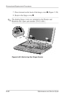
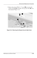
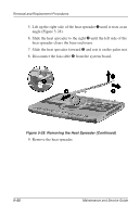
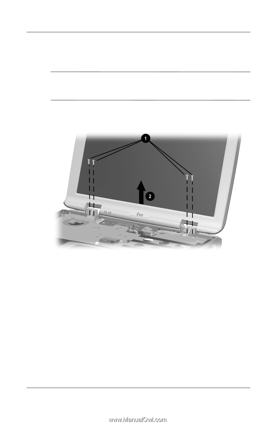
Removal and Replacement Procedures 12. Remove the four silver TM2.0 × 8.0 screws 1 that secure the display to the base enclosure. Ä CAUTION: Secure the display when removing these screws. The display is secured to the computer only by these screws and will fall if not supported during screw removal. 13. Remove the display 2 (Figure 5-23). Figure 5-23. Removing the Display Maintenance and Service Guide 5-27
-
 1
1 -
2
-
3
-
4
-
5
-
6
-
7
-
8
-
9
-
10
-
11
-
12
-
13
-
14
-
15
-
16
-
17
-
18
-
19
-
20
-
21
-
22
-
23
-
24
-
25
-
26
-
27
-
28
-
29
-
30
-
31
-
32
-
33
-
34
-
35
-
36
-
37
-
38
-
39
-
40
-
41
-
42
-
43
-
44
-
45
-
46
-
47
-
48
-
49
-
50
-
51
-
52
-
53
-
54
-
55
-
56
-
57
-
58
-
59
-
60
-
61
-
62
-
63
-
64
-
65
-
66
-
67
-
68
-
69
-
70
-
71
-
72
-
73
-
74
-
75
-
76
-
77
-
78
-
79
-
80
-
81
-
82
-
83
-
84
-
85
-
86
-
87
-
88
-
89
-
 90
90 -
 91
91 -
 92
92 -
 93
93 -
 94
94 -
 95
95 -
 96
96 -
 97
97 -
 98
98 -
 99
99 -
 100
100 -
101
-
102
-
103
-
104
-
105
-
106
-
107
-
108
-
109
-
110
-
111
-
112
-
113
-
114
-
115
-
116
-
117
-
118
-
119
-
120
-
121
-
122
-
123
-
124
-
125
-
126
-
127
-
128
-
129
-
130
-
131
-
132
-
133
-
134
-
135
-
136
-
137
-
138
-
139
-
140
-
141
-
142
-
143
-
144
-
145
-
146
-
147
-
148
-
149
-
150
-
151
-
152
-
153
-
154
-
155
-
156
-
157
-
158
-
159
-
160
-
161
-
162
-
163
-
164
-
165
-
166
-
167
-
168
-
169
-
170
-
171
-
172
-
173
-
174
-
175
-
176
-
177
-
178
-
179
-
180
-
181
-
182
-
183
 |
 |
Removal and Replacement Procedures
Maintenance and Service Guide
5–27
12. Remove the four silver TM2.0 × 8.0 screws
1
that secure the
display to the base enclosure.
Ä
CAUTION:
Secure the display when removing these screws. The
display is secured to the computer only by these screws and will fall
if not supported during screw removal.
13. Remove the display
2
(Figure 5-23).
Figure 5-23. Removing the Display