Compaq Evo Notebook PC n115 Compaq Evo N115 Series Maintenance and Service Gui - Page 80
Removing the Memory Expansion, Compartment Cover, rests at an angle
 |
View all Compaq Evo Notebook PC n115 manuals
Add to My Manuals
Save this manual to your list of manuals |
Page 80 highlights
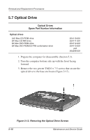
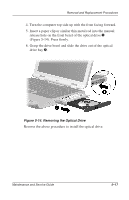
Removal and Replacement Procedures 1. Prepare the computer for disassembly (Section 5.3). 2. Turn the computer bottom side up with the front facing forward. 3. Remove the black PM2.0 × 5.0 screw 1 that secures the memory expansion compartment cover to the base enclosure (Figure 5-9). 4. Swing the left side of the cover up and to the right until it rests at an angle 2. 5. Lift the cover straight up and remove it 3. Figure 5-9. Removing the Memory Expansion Compartment Cover ✎ The memory expansion compartment cover is included in the Plastics and Hardware Kit (spare part number 254121-001). 5-12 Maintenance and Service Guide
-
 1
1 -
2
-
3
-
4
-
5
-
6
-
7
-
8
-
9
-
10
-
11
-
12
-
13
-
14
-
15
-
16
-
17
-
18
-
19
-
20
-
21
-
22
-
23
-
24
-
25
-
26
-
27
-
28
-
29
-
30
-
31
-
32
-
33
-
34
-
35
-
36
-
37
-
38
-
39
-
40
-
41
-
42
-
43
-
44
-
45
-
46
-
47
-
48
-
49
-
50
-
51
-
52
-
53
-
54
-
55
-
56
-
57
-
58
-
59
-
60
-
61
-
62
-
63
-
64
-
65
-
66
-
67
-
68
-
69
-
70
-
71
-
72
-
73
-
74
-
 75
75 -
 76
76 -
 77
77 -
 78
78 -
 79
79 -
 80
80 -
 81
81 -
 82
82 -
 83
83 -
 84
84 -
 85
85 -
86
-
87
-
88
-
89
-
90
-
91
-
92
-
93
-
94
-
95
-
96
-
97
-
98
-
99
-
100
-
101
-
102
-
103
-
104
-
105
-
106
-
107
-
108
-
109
-
110
-
111
-
112
-
113
-
114
-
115
-
116
-
117
-
118
-
119
-
120
-
121
-
122
-
123
-
124
-
125
-
126
-
127
-
128
-
129
-
130
-
131
-
132
-
133
-
134
-
135
-
136
-
137
-
138
-
139
-
140
-
141
-
142
-
143
-
144
-
145
-
146
-
147
-
148
-
149
-
150
-
151
-
152
-
153
-
154
-
155
-
156
-
157
-
158
-
159
-
160
-
161
-
162
-
163
-
164
-
165
-
166
-
167
-
168
-
169
-
170
-
171
-
172
-
173
-
174
-
175
-
176
-
177
-
178
-
179
-
180
-
181
-
182
-
183
 |
 |

5–12
Maintenance and Service Guide
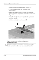
Removal and Replacement Procedures
1. Prepare the computer for disassembly (Section 5.3).
2. Turn the computer bottom side up with the front
facing forward.
3. Remove the black PM2.0 × 5.0 screw
1
that secures the
memory expansion compartment cover to the base enclosure
(Figure 5-9).
4. Swing the left side of the cover up and to the right until it
rests at an angle
2
.
5. Lift the cover straight up and remove it
3
.
Figure 5-9. Removing the Memory Expansion
Compartment Cover
✎
The memory expansion compartment cover is included in the
Plastics and Hardware Kit (spare part number 254121-001).