Compaq Evo Notebook PC n115 Compaq Evo N115 Series Maintenance and Service Gui - Page 91
Remove the LED cover Removing the Hinge Cover Screws
 |
View all Compaq Evo Notebook PC n115 manuals
Add to My Manuals
Save this manual to your list of manuals |
Page 91 highlights
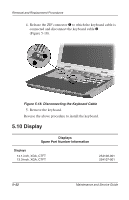
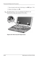
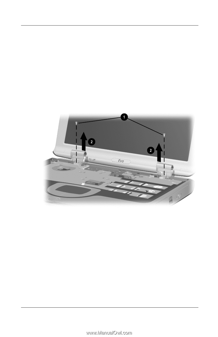
Removal and Replacement Procedures 1. Prepare the computer for disassembly (Section 5.3). 2. Remove the LED cover (Section 5.8). 3. Remove the keyboard (Section 5.9). 4. Remove the two silver TM2.0 × 5.0 screws 1 that secure the hinge covers to the base enclosure (Figure 5-19). 5. Lift the front edge of the hinge cover 2 until it separates from the base enclosure. Figure 5-19. Removing the Hinge Cover Screws 6. Position the display so it rests at a 90-degree angle in relationship to the work surface. Maintenance and Service Guide 5-23
-
 1
1 -
2
-
3
-
4
-
5
-
6
-
7
-
8
-
9
-
10
-
11
-
12
-
13
-
14
-
15
-
16
-
17
-
18
-
19
-
20
-
21
-
22
-
23
-
24
-
25
-
26
-
27
-
28
-
29
-
30
-
31
-
32
-
33
-
34
-
35
-
36
-
37
-
38
-
39
-
40
-
41
-
42
-
43
-
44
-
45
-
46
-
47
-
48
-
49
-
50
-
51
-
52
-
53
-
54
-
55
-
56
-
57
-
58
-
59
-
60
-
61
-
62
-
63
-
64
-
65
-
66
-
67
-
68
-
69
-
70
-
71
-
72
-
73
-
74
-
75
-
76
-
77
-
78
-
79
-
80
-
81
-
82
-
83
-
84
-
85
-
 86
86 -
 87
87 -
 88
88 -
 89
89 -
 90
90 -
 91
91 -
 92
92 -
 93
93 -
 94
94 -
 95
95 -
 96
96 -
97
-
98
-
99
-
100
-
101
-
102
-
103
-
104
-
105
-
106
-
107
-
108
-
109
-
110
-
111
-
112
-
113
-
114
-
115
-
116
-
117
-
118
-
119
-
120
-
121
-
122
-
123
-
124
-
125
-
126
-
127
-
128
-
129
-
130
-
131
-
132
-
133
-
134
-
135
-
136
-
137
-
138
-
139
-
140
-
141
-
142
-
143
-
144
-
145
-
146
-
147
-
148
-
149
-
150
-
151
-
152
-
153
-
154
-
155
-
156
-
157
-
158
-
159
-
160
-
161
-
162
-
163
-
164
-
165
-
166
-
167
-
168
-
169
-
170
-
171
-
172
-
173
-
174
-
175
-
176
-
177
-
178
-
179
-
180
-
181
-
182
-
183
 |
 |
Removal and Replacement Procedures
Maintenance and Service Guide
5–23
1. Prepare the computer for disassembly (Section 5.3).
2. Remove the LED cover (Section 5.8).
3. Remove the keyboard (Section 5.9).
4. Remove the two silver TM2.0 × 5.0 screws
1
that secure the
hinge covers to the base enclosure (Figure 5-19).
5.
Lift the front edge of the hinge cover
2
until it separates from
the base enclosure.
Figure 5-19. Removing the Hinge Cover Screws
6. Position the display so it rests at a 90-degree angle in
relationship to the work surface.