Compaq Evo Notebook PC n115 Compaq Evo N115 Series Maintenance and Service Gui - Page 117
Diskette drive Top cover
 |
View all Compaq Evo Notebook PC n115 manuals
Add to My Manuals
Save this manual to your list of manuals |
Page 117 highlights
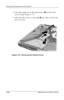
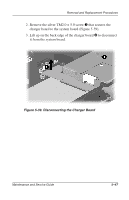
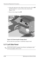
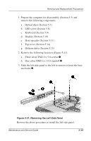
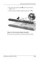
Removal and Replacement Procedures 1. Prepare the computer for disassembly (Section 5.3) and remove the following components: a. Optical drive (Section 5.7) b. LED cover (Section 5.8) c. Keyboard (Section 5.9) d. Display (Section 5.10) e. Heat spreader (Section 5.11) f. Top cover (Section 5.14) g. Diskette drive (Section 5.15) 2. Remove the following fasteners (Figure 5-41): a. Three silver TM2.0 × 5.0 screws 1 b. One silver HM5.0 × 13.0 standoff 2 3. Slide the left side panel to the left to remove it from the base enclosure 3. Figure 5-41. Removing the Left Side Panel Reverse the above procedure to install the left side panel. Maintenance and Service Guide 5-49
-
 1
1 -
2
-
3
-
4
-
5
-
6
-
7
-
8
-
9
-
10
-
11
-
12
-
13
-
14
-
15
-
16
-
17
-
18
-
19
-
20
-
21
-
22
-
23
-
24
-
25
-
26
-
27
-
28
-
29
-
30
-
31
-
32
-
33
-
34
-
35
-
36
-
37
-
38
-
39
-
40
-
41
-
42
-
43
-
44
-
45
-
46
-
47
-
48
-
49
-
50
-
51
-
52
-
53
-
54
-
55
-
56
-
57
-
58
-
59
-
60
-
61
-
62
-
63
-
64
-
65
-
66
-
67
-
68
-
69
-
70
-
71
-
72
-
73
-
74
-
75
-
76
-
77
-
78
-
79
-
80
-
81
-
82
-
83
-
84
-
85
-
86
-
87
-
88
-
89
-
90
-
91
-
92
-
93
-
94
-
95
-
96
-
97
-
98
-
99
-
100
-
101
-
102
-
103
-
104
-
105
-
106
-
107
-
108
-
109
-
110
-
111
-
 112
112 -
 113
113 -
 114
114 -
 115
115 -
 116
116 -
 117
117 -
 118
118 -
 119
119 -
 120
120 -
 121
121 -
 122
122 -
123
-
124
-
125
-
126
-
127
-
128
-
129
-
130
-
131
-
132
-
133
-
134
-
135
-
136
-
137
-
138
-
139
-
140
-
141
-
142
-
143
-
144
-
145
-
146
-
147
-
148
-
149
-
150
-
151
-
152
-
153
-
154
-
155
-
156
-
157
-
158
-
159
-
160
-
161
-
162
-
163
-
164
-
165
-
166
-
167
-
168
-
169
-
170
-
171
-
172
-
173
-
174
-
175
-
176
-
177
-
178
-
179
-
180
-
181
-
182
-
183
 |
 |

Removal and Replacement Procedures
Maintenance and Service Guide
5–49
1. Prepare the computer for disassembly (Section 5.3) and
remove the following components:
a.
Optical drive (Section 5.7)
b.
LED cover (Section 5.8)
c.
Keyboard (Section 5.9)
d.
Display (Section 5.10)
e.
Heat spreader (Section 5.11)
f.
Top cover (Section 5.14)
g.
Diskette drive (Section 5.15)
2. Remove the following fasteners (Figure 5-41):
a.
Three silver TM2.0 × 5.0 screws
1
b.
One silver HM5.0 × 13.0 standoff
2
3. Slide the left side panel to the left to remove it from the base
enclosure
3
.
Figure 5-41. Removing the Left Side Panel
Reverse the above procedure to install the left side panel.