Compaq Evo Notebook PC n115 Compaq Evo N115 Series Maintenance and Service Gui - Page 84
Optical Drive
 |
View all Compaq Evo Notebook PC n115 manuals
Add to My Manuals
Save this manual to your list of manuals |
Page 84 highlights
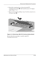
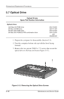
Removal and Replacement Procedures 5.7 Optical Drive Optical Drives Spare Part Number Information Optical drives 24X Max CD-ROM drive 8X Max CD-RW drive 8X Max DVD-ROM drive 8X Max DVD-ROM/CD-RW combination drive 254110-001 254111-001 254112-001 254113-001 and 264298-001 1. Prepare the computer for disassembly (Section 5.3). 2. Turn the computer bottom side up with the front facing forward. 3. Remove the two pewter TM2.0 × 7.5 screws that secure the optical drive to the base enclosure (Figure 5-13). Figure 5-13. Removing the Optical Drive Screws 5-16 Maintenance and Service Guide
-
 1
1 -
2
-
3
-
4
-
5
-
6
-
7
-
8
-
9
-
10
-
11
-
12
-
13
-
14
-
15
-
16
-
17
-
18
-
19
-
20
-
21
-
22
-
23
-
24
-
25
-
26
-
27
-
28
-
29
-
30
-
31
-
32
-
33
-
34
-
35
-
36
-
37
-
38
-
39
-
40
-
41
-
42
-
43
-
44
-
45
-
46
-
47
-
48
-
49
-
50
-
51
-
52
-
53
-
54
-
55
-
56
-
57
-
58
-
59
-
60
-
61
-
62
-
63
-
64
-
65
-
66
-
67
-
68
-
69
-
70
-
71
-
72
-
73
-
74
-
75
-
76
-
77
-
78
-
 79
79 -
 80
80 -
 81
81 -
 82
82 -
 83
83 -
 84
84 -
 85
85 -
 86
86 -
 87
87 -
 88
88 -
 89
89 -
90
-
91
-
92
-
93
-
94
-
95
-
96
-
97
-
98
-
99
-
100
-
101
-
102
-
103
-
104
-
105
-
106
-
107
-
108
-
109
-
110
-
111
-
112
-
113
-
114
-
115
-
116
-
117
-
118
-
119
-
120
-
121
-
122
-
123
-
124
-
125
-
126
-
127
-
128
-
129
-
130
-
131
-
132
-
133
-
134
-
135
-
136
-
137
-
138
-
139
-
140
-
141
-
142
-
143
-
144
-
145
-
146
-
147
-
148
-
149
-
150
-
151
-
152
-
153
-
154
-
155
-
156
-
157
-
158
-
159
-
160
-
161
-
162
-
163
-
164
-
165
-
166
-
167
-
168
-
169
-
170
-
171
-
172
-
173
-
174
-
175
-
176
-
177
-
178
-
179
-
180
-
181
-
182
-
183
 |
 |

5–16
Maintenance and Service Guide
Removal and Replacement Procedures
5.7 Optical Drive
1. Prepare the computer for disassembly (Section 5.3).
2. Turn the computer bottom side up with the front facing
forward.
3. Remove the two pewter TM2.0 × 7.5 screws that secure the
optical drive to the base enclosure (Figure 5-13).
Figure 5-13. Removing the Optical Drive Screws
Optical Drives
Spare Part Number Information
Optical drives
24X Max CD-ROM drive
8X Max CD-RW drive
8X Max DVD-ROM drive
8X Max DVD-ROM/CD-RW combination drive
254110-001
254111-001
254112-001
254113-001
and
264298-001