D-Link DSN-5000-10 Hardware Reference Guide for DSN-5000-10 - Page 14
System Overview
 |
UPC - 790069324024
View all D-Link DSN-5000-10 manuals
Add to My Manuals
Save this manual to your list of manuals |
Page 14 highlights
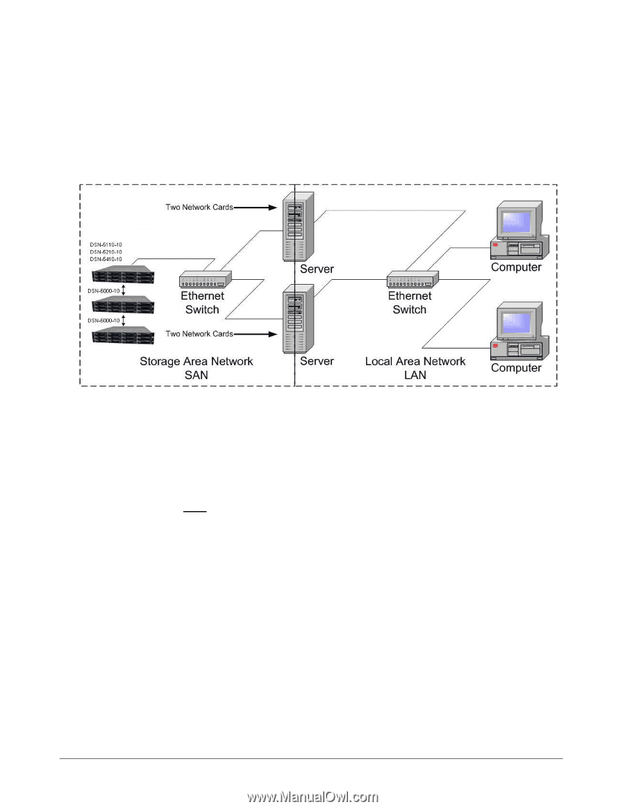
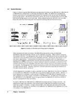
1.3 System Overview Figure 1-1 shows a typical DSN-5000 series storage system (primary array DSN-5110-10, DSN-5210-10 or DSN-5410-10) configuration in a Storage Area Network (SAN). The SAN shown is an Ethernet network used solely for exchanging data between the customer's host servers and the DSN-5000 series storage system. The Ethernet bandwidth used by the servers exchanging data with the DSN5000 series storage system can be very high. Using a separate Ethernet network to act as a SAN keeps that data from interfering with the customer's existing LAN and improves security. Figure 1-1. Example of a DSN-5000 series Storage System Configuration When equipped with dual controllers, the DSN-5000 series primary array provides High Availability (HA) with automatic failover to the redundant controller. When a failure occurs on the primary controller, the Management Port and all of the iSCSI data ports will be automatically redirected to the equivalent ports on the redundant controller, without any interruption to your host server applications. To accomplish the redirection of network traffic on those ports, a network switch must be used between the host server(s) and both of the controllers found in the DSN-5000 series primary array prior to system startup to allow the automatic re-direction of the network connections to the redundant controller when a failure occurs on the primary controller. For example, the Management Port network connection on both controllers must be connected to the same network switch. Similarly, Data Port 0 on both controllers must also be connected to the same network switch, and so on. A Field Upgrade Kit is available to add a redundant controller (DSN-510 for the 5110-10, DSN-520 for the 5210-10 or DSN-540 for the 5410-10) to any existing single-controller system. Similarly, a Field Upgrade Kit is available to add a second I/O Module to the DSN-5000-10 expansion array (The expansion array with a single I/O module is the DSN-5000-10. An additional I/O module for the DSN-5000-10 is the DSN-500), which is required when the DSN-5110-10, 5210-10 or 5410-10 system is equipped with dual controllers. To clarify: DSN-5110-10, DSN-5210-10 or DSN-5410-10 systems all have a single controller. For additional storage array expansion, each would require a DSN-5000-10 expansion array which itself has a single I/O module. A single external SAS to mini-SAS cable (provided with the DSN5000-10) will then connect the controller in the DSN-5110-10, DSN-5210-10 or DSN-5410-10 to the I/O module in the DSN-5000-10. 6 Chapter 1 Introduction
-
 1
1 -
2
-
3
-
4
-
5
-
6
-
7
-
8
-
 9
9 -
 10
10 -
 11
11 -
 12
12 -
 13
13 -
 14
14 -
 15
15 -
 16
16 -
 17
17 -
 18
18 -
 19
19 -
20
-
21
-
22
-
23
-
24
-
25
-
26
-
27
-
28
-
29
-
30
-
31
-
32
-
33
-
34
-
35
-
36
-
37
-
38
-
39
-
40
-
41
-
42
-
43
-
44
-
45
-
46
-
47
-
48
-
49
-
50
-
51
-
52
 |
 |