D-Link DSN-5000-10 Hardware Reference Guide for DSN-5000-10 - Page 50
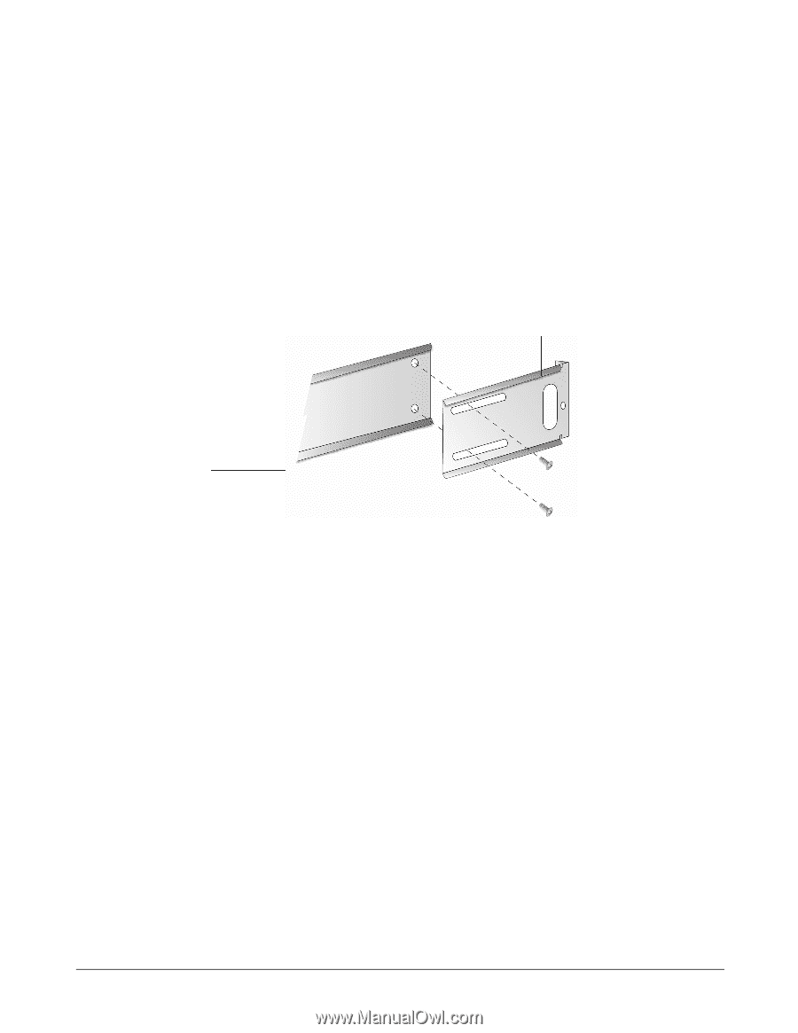
B-2. Securing the Main and Rear Rails
 |
UPC - 790069324024
View all D-Link DSN-5000-10 manuals
Add to My Manuals
Save this manual to your list of manuals |
Page 50 highlights
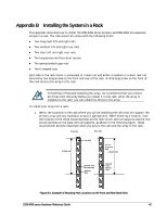
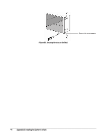
2. Assemble the rails that will accommodate the array in the rack. The long main left and right rails are used in all installations (these rails have a bottom piece on which the array sits in the rack). However, you must determine whether to use the two medium rear rails or the two short rear rails based on the depth of your rack. Then assemble the main and rear rails together at the exact length to match the distance between the front and rear vertical supports of the rack. 3. After determining which rear rails to use, orient the left rear rail so its flange faces outwardly to the left and orient the left main rail so the bottom lip (which will support the array) protrudes inwardly, as shown in the following figure. Then secure the left rear rail to the left main rail using two of the supplied short screws (the screws go through the slots in the rear rail and into the threaded section of the long rail, as shown in the following figure). Flange on rear rail is facing outwardly Bottom on main rail is protruding inwardly Figure B-2. Securing the Main and Rear Rails 4. Orient the right rear rail so its flange faces outwardly to the right and orient the right main rail so the bottom lip protrudes inwardly. Then secure the right rear rail to the right main rail using the remaining two long or short screws (the screws go through the slots in the rear rail into the threaded section of the long rail). 5. Orient the right rear rail so its flange faces outwardly to the right and orient the right main rail so the bottom piece protrudes inwardly. Then secure the right rear rail to the right main rail using the remaining two short screws (the screws go through the slots in the rear rail into the threaded section of the long rail. 6. Insert the rails into the rack and secure the rails to the vertical supports using one of the following methods: If the rack has square punchout holes, secure the rails using the supplied long screws with the supplied snap-in spring-loaded cage nuts. Attach the nuts to the three rail holes (top, bottom, and second-from-the-bottom) on the front left and right sides of the rack. Then attach nuts to the two middle holes on the rear of the rack. If the rack holes are unthreaded circular holes, use the long screws with the supplied Eshaped nuts. Attach E-shaped nuts to the three rail holes (top, bottom, and secondfrom-the-bottom) on the front left and right sides of the rack. Then attach E-shaped nuts to the two middle holes on the rear of the rack. If the rack has round and threaded holes, secure the rails using the supplied long screws only (there is no need to use the snap-in spring-loaded cage nuts and the E-shaped devices). 42 Appendix B Installing the System in a Rack
-
 1
1 -
2
-
3
-
4
-
5
-
6
-
7
-
8
-
9
-
10
-
11
-
12
-
13
-
14
-
15
-
16
-
17
-
18
-
19
-
20
-
21
-
22
-
23
-
24
-
25
-
26
-
27
-
28
-
29
-
30
-
31
-
32
-
33
-
34
-
35
-
36
-
37
-
38
-
39
-
40
-
41
-
42
-
43
-
44
-
 45
45 -
 46
46 -
 47
47 -
 48
48 -
 49
49 -
 50
50 -
 51
51 -
 52
52
 |
 |