D-Link DSN-5000-10 Hardware Reference Guide for DSN-5000-10 - Page 49
Appendix B, Installing the System in a Rack
 |
UPC - 790069324024
View all D-Link DSN-5000-10 manuals
Add to My Manuals
Save this manual to your list of manuals |
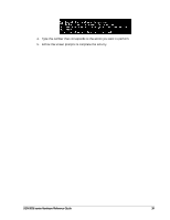
Page 49 highlights
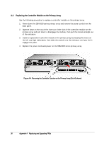
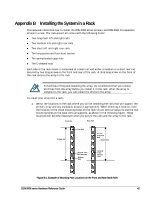
Appendix B Installing the System in a Rack This appendix describes how to install the DSN-5000 series primary and DSN-5000-10 expansion arrays in a rack. The rack-mount kit comes with the following items: Two long main left and right rails Two medium left and right rear rails Two short left and right rear rails Ten long screws and four short screws Ten spring-loaded cage nuts Ten E-shaped nuts Each side of the rack mount is composed of a main rail and either a medium or a short rear rail secured by two long screws on the front and rear of the rack. A third long screw on the front of the rack secures the array to the rack. To facilitate lifting and installing the array, we recommend that you remove all drives from the array before you install it in the rack. After the array is installed in the rack, you can install the drives in the array. To install your array into a rack: 1. Select the locations in the rack where you will be installing the rails that will support the primary array and any expansion arrays (if appropriate). When selecting a location, note the location of the three mounting holes on the rack's front vertical supports and the two mounting holes on the back vertical supports, as shown in the following figure. These locations will become important when you secure the rails and the array to the rack. Front Rail Rear Rail 2 Rack Units Top Hole Secondfrom-Top Hole 2 Rack Units Second-fromBottom Hole Bottom Hole SecondfromBottom Hole Figure B-1. Example of Mounting Hole Locations on the Front and Rear Rack Rails DSN-5000 series Hardware Reference Guide 41
-
 1
1 -
2
-
3
-
4
-
5
-
6
-
7
-
8
-
9
-
10
-
11
-
12
-
13
-
14
-
15
-
16
-
17
-
18
-
19
-
20
-
21
-
22
-
23
-
24
-
25
-
26
-
27
-
28
-
29
-
30
-
31
-
32
-
33
-
34
-
35
-
36
-
37
-
38
-
39
-
40
-
41
-
42
-
43
-
 44
44 -
 45
45 -
 46
46 -
 47
47 -
 48
48 -
 49
49 -
 50
50 -
 51
51 -
 52
52
 |
 |