D-Link DSN-5000-10 Hardware Reference Guide for DSN-5000-10 - Page 51
B-3. Securing the Rails to the Rack, B-4. Sliding the Array onto the Rails
 |
UPC - 790069324024
View all D-Link DSN-5000-10 manuals
Add to My Manuals
Save this manual to your list of manuals |
Page 51 highlights
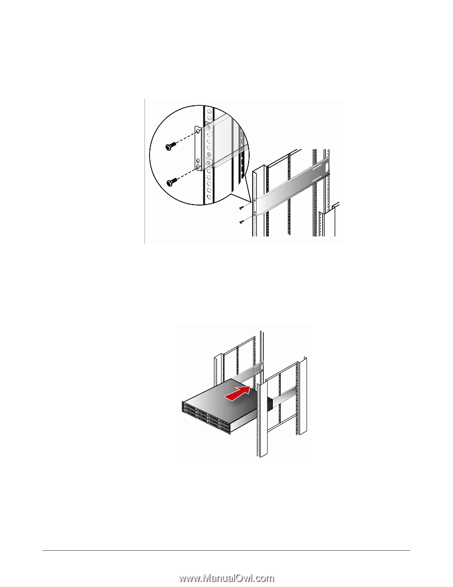
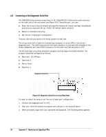
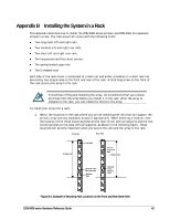
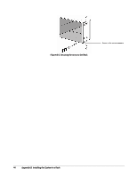
7. Secure the rails to the rack by inserting screws in the top and bottom holes on the left and right sides on the front of the rack (as shown in the following figure). Do not insert screws into the second-from-the-bottom hole at this time. Figure B-3. Securing the Rails to the Rack 8. Insert screws into the middle two rear rail holes. 9. Verify that the rails are installed securely in the rack. 10. Carefully slide the array onto the rails, pushing it back until the flanges on the front of the chassis meet the vertical supports. Figure B-4. Sliding the Array onto the Rails 11. Locate the second-from-the-bottom hole on the front right side of the rack. This hole should be aligned with a hole in the flange or "ear" on the right front of the array. Place a screw in the hole in the array, then insert a screwdriver through the hole in the front flange of the array and tighten the screw to secure the array to the vertical supports, as shown in the following figure. Repeat this step using another screw and the second-from-the-bottom hole on the left side of the rack. DSN-5000 series Hardware Reference Guide 43
-
 1
1 -
2
-
3
-
4
-
5
-
6
-
7
-
8
-
9
-
10
-
11
-
12
-
13
-
14
-
15
-
16
-
17
-
18
-
19
-
20
-
21
-
22
-
23
-
24
-
25
-
26
-
27
-
28
-
29
-
30
-
31
-
32
-
33
-
34
-
35
-
36
-
37
-
38
-
39
-
40
-
41
-
42
-
43
-
44
-
45
-
 46
46 -
 47
47 -
 48
48 -
 49
49 -
 50
50 -
 51
51 -
 52
52
 |
 |