D-Link DSN-5000-10 Hardware Reference Guide for DSN-5000-10 - Page 36
Expansion Array Rear Panel Components, Site, Safety, and Rack-Mount Considerations, Unpacking
 |
UPC - 790069324024
View all D-Link DSN-5000-10 manuals
Add to My Manuals
Save this manual to your list of manuals |
Page 36 highlights
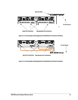
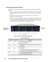
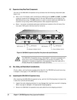
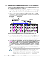
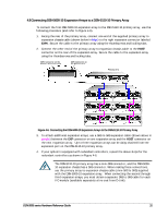
4.2 Expansion Array Rear Panel Components The rear of the DSN-5000-10 expansion array enclosure has the following components (see Figure 4-4): One or two I/O modules, each containing two SAS connectors (HOST and EXP); the HOST connector connects the expansion array to the mini-SAS connector on the back of the DSN-5000 primary array. The EXP connector is used to connect additional DSN-5000-10 expansion arrays using a SAS-to-SAS expansion cable (supplied separately). Power - two power receptacles and power switches are located on the left side of the rear panel. Both power switches must be turned on. HOST Connector EXP Connector HOST Connector EXP Connector Redundant I/O Module in Slot #1 Primary I/O Module in Slot #0 Figure 4-4. DSN-5000-10 expansion array Rear View (shown with dual I/O Modules) The DSN-5000-10 expansion array is "HA-capable" and can be equipped with either one or two I/O modules (DSN-500 is the second I/O module). The redundant I/O module is required in the Expansion Array when used with a Primary Array that is equipped with dual controllers. 4.3 Site, Safety, and Rack-Mount Considerations All site, safety, and rack-mount considerations listed for the DSN-5000 series primary array in Chapter 3 also apply to the DSN-5000-10 expansion array. 4.4 Unpacking the DSN-5000-10 Expansion Array After receiving the DSN-5000-10 expansion array, perform the following steps to ensure that it and other contents arrived safely. 1. Inspect the outer shipping container for any damage that may have occurred in shipping. Report any sign of damage to the appropriate shipping agency. 2. Remove the DSN-5000-10 expansion array and cables from the shipping container. 28 Chapter 4 DSN-5000 Expansion Array Layout and Installation
-
 1
1 -
2
-
3
-
4
-
5
-
6
-
7
-
8
-
9
-
10
-
11
-
12
-
13
-
14
-
15
-
16
-
17
-
18
-
19
-
20
-
21
-
22
-
23
-
24
-
25
-
26
-
27
-
28
-
29
-
30
-
 31
31 -
 32
32 -
 33
33 -
 34
34 -
 35
35 -
 36
36 -
 37
37 -
 38
38 -
 39
39 -
 40
40 -
 41
41 -
42
-
43
-
44
-
45
-
46
-
47
-
48
-
49
-
50
-
51
-
52
 |
 |