D-Link DSN-5000-10 Hardware Reference Guide for DSN-5000-10 - Page 35
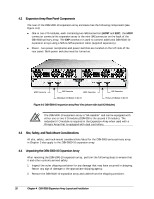
Close-up View of the Lever Release Button and Status LEDs on a Drive Carrier
 |
UPC - 790069324024
View all D-Link DSN-5000-10 manuals
Add to My Manuals
Save this manual to your list of manuals |
Page 35 highlights
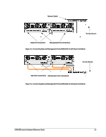
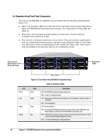
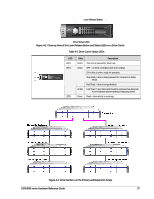
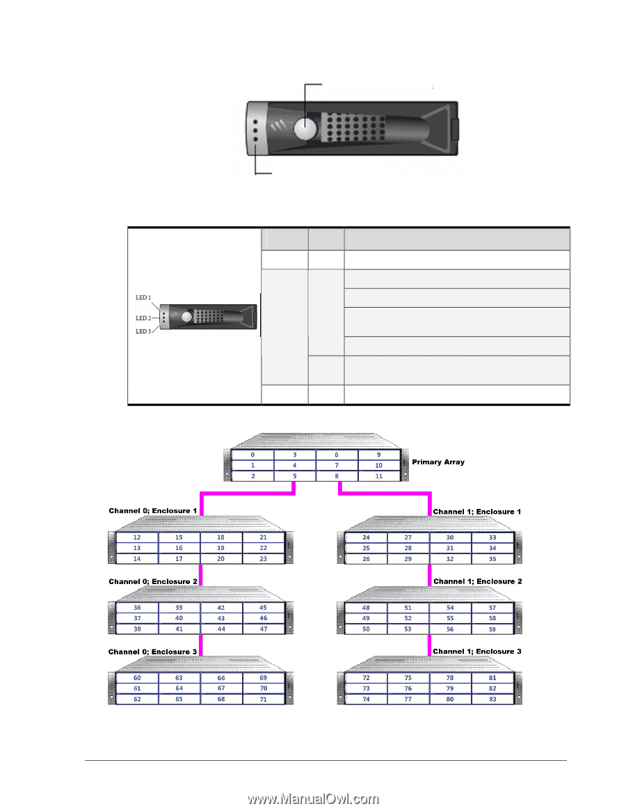
Lever Release Button Drive Status LEDs Figure 4-2. Close-up View of the Lever Release Button and Status LEDs on a Drive Carrier Table 4-2. Drive Carrier Status LEDs LED LED 1 LED 2 LED3 Color Description Green This LED is reserved for future use. Green OFF = no drive is installed (drive slot is empty). ON = drive is online, ready for operation. Slow Flash = drive is being prepared for removal or is being rebuilt. Fast Flash = drive is being identified. Amber Fast Flash = drive failed and should be replaced (see Appendix A for information about installing or replacing drives) Green Flash = drive activity is occurring. Figure 4-3. Drive Numbers on the Primary and Expansion Arrays DSN-5000 series Hardware Reference Guide 27
-
 1
1 -
2
-
3
-
4
-
5
-
6
-
7
-
8
-
9
-
10
-
11
-
12
-
13
-
14
-
15
-
16
-
17
-
18
-
19
-
20
-
21
-
22
-
23
-
24
-
25
-
26
-
27
-
28
-
29
-
 30
30 -
 31
31 -
 32
32 -
 33
33 -
 34
34 -
 35
35 -
 36
36 -
 37
37 -
 38
38 -
 39
39 -
 40
40 -
41
-
42
-
43
-
44
-
45
-
46
-
47
-
48
-
49
-
50
-
51
-
52
 |
 |
DSN-5000 series Hardware Reference Guide
27
Figure 4-2. Close-up View of the Lever Release Button and Status LEDs on a Drive Carrier
Table 4-2. Drive Carrier Status LEDs
LED
Color
Description
LED 1
Green
This LED is reserved for future use.
OFF = no drive is installed (drive slot is empty).
ON = drive is online, ready for operation.
Slow Flash = drive is being prepared for removal or is being
rebuilt.
Green
Fast Flash = drive is being identified.
LED 2
Amber
Fast Flash = drive failed and should be replaced (see Appendix
A for information about installing or replacing drives)
LED3
Green
Flash = drive activity is occurring.
Figure 4-3. Drive Numbers on the Primary and Expansion Arrays
Drive Status LEDs
Lever Release Button