D-Link DSN-5000-10 Hardware Reference Guide for DSN-5000-10 - Page 23
Side, Top and Bottom Panel Components
 |
UPC - 790069324024
View all D-Link DSN-5000-10 manuals
Add to My Manuals
Save this manual to your list of manuals |
Page 23 highlights
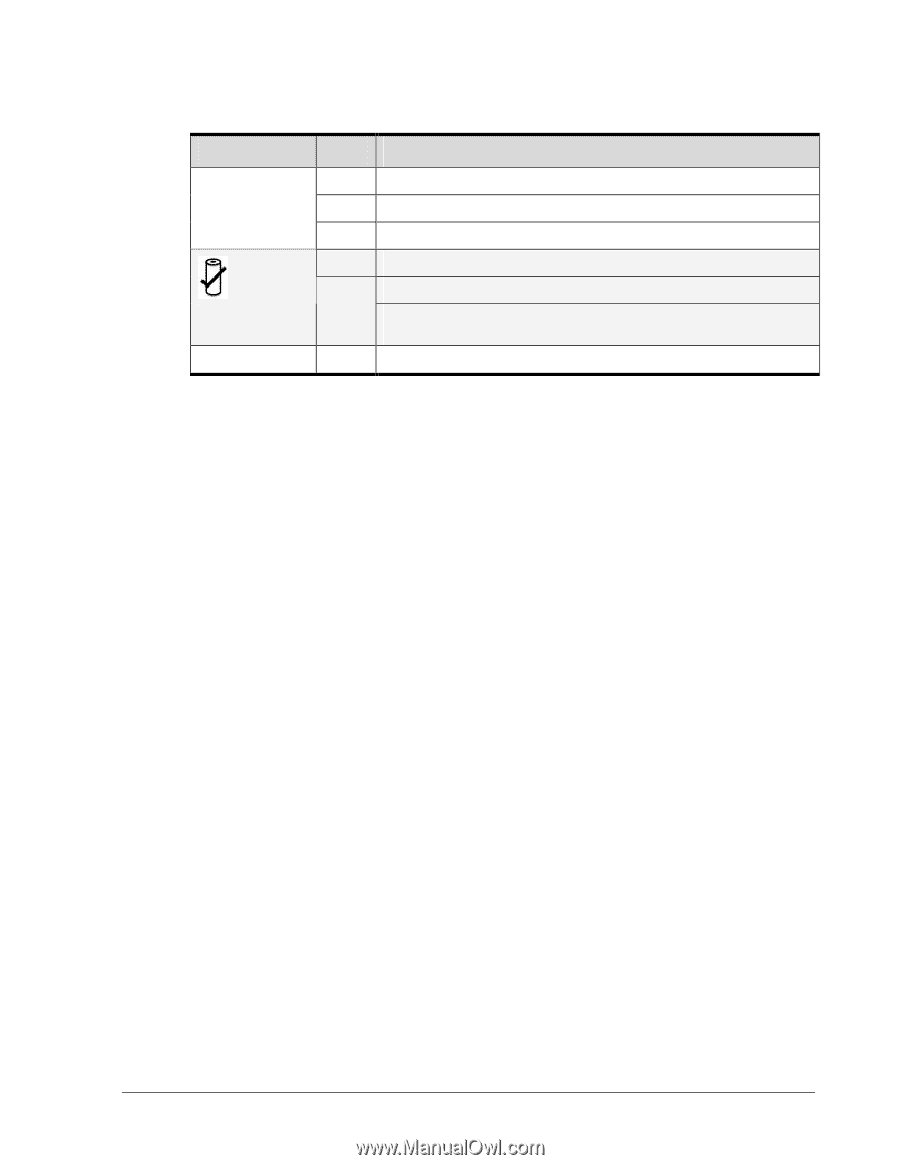
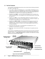
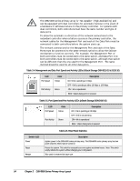
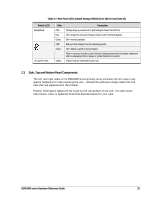
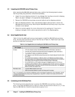
Table 2-7. Rear Panel LEDs (xStack Storage DSN-5110-10, 5210-10 and 5410-10) Switch / LED Ready/Fault "A" and "B" LEDs Color OFF Red Green OFF Green Yellow Description Primary array is powered off or performing its Power On Self Test. ON = a fault has occurred. Please contact D-Link Technical Support. ON = normal operation. Battery is fully charged and not sustaining cache. ON = battery is good or being charged. Flash = contents of system cache memory is being preserved by the battery subsystem after an unexpected loss of power or system failure has occurred. These LEDs are reserved for future use. 2.3 Side, Top and Bottom Panel Components The left and right sides of the DSN-5000 series primary array enclosure do not require any special hardware for rack-mounting the unit - instead the enclosure simply slides into the rails that are supplied with the product. Product information labels will be found on the top surface of the unit. For rack-mount instructions, refer to Appendix B and the documentation for your rack. DSN-5000 series Hardware Reference Guide 15
-
 1
1 -
2
-
3
-
4
-
5
-
6
-
7
-
8
-
9
-
10
-
11
-
12
-
13
-
14
-
15
-
16
-
17
-
 18
18 -
 19
19 -
 20
20 -
 21
21 -
 22
22 -
 23
23 -
 24
24 -
 25
25 -
 26
26 -
 27
27 -
 28
28 -
29
-
30
-
31
-
32
-
33
-
34
-
35
-
36
-
37
-
38
-
39
-
40
-
41
-
42
-
43
-
44
-
45
-
46
-
47
-
48
-
49
-
50
-
51
-
52
 |
 |