Dell Alienware M16 R2 Owners Manual - Page 65
Display assembly, Removing the display assembly
 |
View all Dell Alienware M16 R2 manuals
Add to My Manuals
Save this manual to your list of manuals |
Page 65 highlights
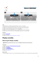
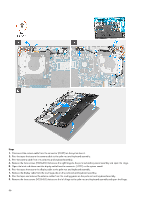
Steps 1. With the display closed, align and place the left hinge cover (L) on the left hinge. 2. Align the screw hole on the left display-hinge cover (L) with the screw hole on the left hinge. 3. Replace the screw (M1.6x2.5) that secures the left display-hinge cover (L) to the left hinge. 4. Align and place the right display-hinge cover (R) on the right hinge. 5. Align the screw hole on the right display-hinge cover (R) with the screw hole on the right hinge. 6. Replace the screw (M1.6x2.5) that secures the right display-hinge cover (R) to the right hinge. Next steps 1. Install the rear I/O cover. 2. Install the base cover. 3. Follow the procedure in After working inside your computer. Display assembly Removing the display assembly CAUTION: The information in this removal section is intended for authorized service technicians only. Prerequisites 1. Follow the procedure in Before working inside your computer. 2. Remove the base cover. 3. Remove the rear I/O cover. 4. Remove the display-hinge covers. 5. Remove the fan and heat-sink assembly. 6. Remove the wireless card. About this task The following image(s) indicate the location of the display assembly and provides a visual representation of the removal procedure. 65
-
 1
1 -
2
-
3
-
4
-
5
-
6
-
7
-
8
-
9
-
10
-
11
-
12
-
13
-
14
-
15
-
16
-
17
-
18
-
19
-
20
-
21
-
22
-
23
-
24
-
25
-
26
-
27
-
28
-
29
-
30
-
31
-
32
-
33
-
34
-
35
-
36
-
37
-
38
-
39
-
40
-
41
-
42
-
43
-
44
-
45
-
46
-
47
-
48
-
49
-
50
-
51
-
52
-
53
-
54
-
55
-
56
-
57
-
58
-
59
-
 60
60 -
 61
61 -
 62
62 -
 63
63 -
 64
64 -
 65
65 -
 66
66 -
 67
67 -
 68
68 -
 69
69 -
 70
70 -
71
-
72
-
73
-
74
-
75
-
76
-
77
-
78
-
79
-
80
-
81
-
82
-
83
-
84
-
85
-
86
-
87
-
88
-
89
-
90
-
91
-
92
-
93
-
94
-
95
-
96
-
97
-
98
-
99
-
100
-
101
-
102
-
103
-
104
-
105
-
106
-
107
-
108
-
109
-
110
 |
 |
