Dell Alienware M16 R2 Owners Manual - Page 68
Steps, CAUTION: To avoid damaging the display
 |
View all Dell Alienware M16 R2 manuals
Add to My Manuals
Save this manual to your list of manuals |
Page 68 highlights
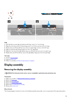
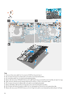
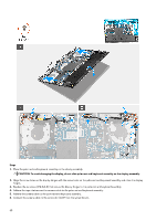
Steps 1. Place the palm rest and keyboard assembly on the display assembly. CAUTION: To avoid damaging the display, do not slide palm rest and keyboard assembly on the display assembly. 2. Align the screw holes on the display hinges with the screw holes on the palm rest and keyboard assembly and close the display hinges. 3. Replace the six screws (M2.5x3.5) that secure the display hinges to the palm rest and keyboard assembly. 4. Adhere the tape that secures the camera cable to the palm rest and keyboard assembly. 5. Adhere the camera cable to the palm rest and keyboard assembly. 6. Connect the camera cable to the connector (CAM1) on the system board. 68
-
 1
1 -
2
-
3
-
4
-
5
-
6
-
7
-
8
-
9
-
10
-
11
-
12
-
13
-
14
-
15
-
16
-
17
-
18
-
19
-
20
-
21
-
22
-
23
-
24
-
25
-
26
-
27
-
28
-
29
-
30
-
31
-
32
-
33
-
34
-
35
-
36
-
37
-
38
-
39
-
40
-
41
-
42
-
43
-
44
-
45
-
46
-
47
-
48
-
49
-
50
-
51
-
52
-
53
-
54
-
55
-
56
-
57
-
58
-
59
-
60
-
61
-
62
-
 63
63 -
 64
64 -
 65
65 -
 66
66 -
 67
67 -
 68
68 -
 69
69 -
 70
70 -
 71
71 -
 72
72 -
 73
73 -
74
-
75
-
76
-
77
-
78
-
79
-
80
-
81
-
82
-
83
-
84
-
85
-
86
-
87
-
88
-
89
-
90
-
91
-
92
-
93
-
94
-
95
-
96
-
97
-
98
-
99
-
100
-
101
-
102
-
103
-
104
-
105
-
106
-
107
-
108
-
109
-
110
 |
 |

Steps
1.
Place the palm rest and keyboard assembly on the display assembly.
CAUTION: To avoid damaging the display, do not slide palm rest and keyboard assembly on the display assembly.
2.
Align the screw holes on the display hinges with the screw holes on the palm rest and keyboard assembly and close the display
hinges.
3.
Replace the six screws (M2.5x3.5) that secure the display hinges to the palm rest and keyboard assembly.
4.
Adhere the tape that secures the camera cable to the palm rest and keyboard assembly.
5.
Adhere the camera cable to the palm rest and keyboard assembly.
6.
Connect the camera cable to the connector (CAM1) on the system board.
68