Dell Alienware M16 R2 Owners Manual - Page 71
Display-cable connector LCD1, Camera-cable connector CAM1
 |
View all Dell Alienware M16 R2 manuals
Add to My Manuals
Save this manual to your list of manuals |
Page 71 highlights
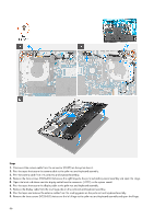
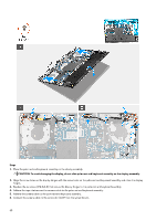
Prerequisites 1. Follow the procedure in Before working inside your computer. 2. Remove the base cover. 3. Remove the rear I/O cover. 4. Remove the battery. 5. Remove the memory. 6. Remove the solid-state drive. 7. Remove the wireless card. 8. Remove the fan and heat-sink assembly. 9. Remove the power-adapter port. 10. Remove the Type-C bracket. About this task The following image indicates the connectors on your system board. 1. Camera-cable connector (CAM1) 2. Power-button cable connector (PWR1) 3. Display-cable connector (LCD1) 4. Left-fan cable connector (FAN1) 5. Wireless-card slot (WLAN1) 71
-
 1
1 -
2
-
3
-
4
-
5
-
6
-
7
-
8
-
9
-
10
-
11
-
12
-
13
-
14
-
15
-
16
-
17
-
18
-
19
-
20
-
21
-
22
-
23
-
24
-
25
-
26
-
27
-
28
-
29
-
30
-
31
-
32
-
33
-
34
-
35
-
36
-
37
-
38
-
39
-
40
-
41
-
42
-
43
-
44
-
45
-
46
-
47
-
48
-
49
-
50
-
51
-
52
-
53
-
54
-
55
-
56
-
57
-
58
-
59
-
60
-
61
-
62
-
63
-
64
-
65
-
 66
66 -
 67
67 -
 68
68 -
 69
69 -
 70
70 -
 71
71 -
 72
72 -
 73
73 -
 74
74 -
 75
75 -
 76
76 -
77
-
78
-
79
-
80
-
81
-
82
-
83
-
84
-
85
-
86
-
87
-
88
-
89
-
90
-
91
-
92
-
93
-
94
-
95
-
96
-
97
-
98
-
99
-
100
-
101
-
102
-
103
-
104
-
105
-
106
-
107
-
108
-
109
-
110
 |
 |

Prerequisites
1.
Follow the procedure in
Before working inside your computer
.
2.
Remove the
base cover
.
3.
Remove the
rear I/O cover
.
4.
Remove the
battery
.
5.
Remove the
memory
.
6.
Remove the
solid-state drive
.
7.
Remove the
wireless card
.
8.
Remove the
fan and heat-sink assembly
.
9.
Remove the
power-adapter port
.
10.
Remove the
Type-C bracket
.
About this task
The following image indicates the connectors on your system board.
1.
Camera-cable connector (CAM1)
2.
Power-button cable connector (PWR1)
3.
Display-cable connector (LCD1)
4.
Left-fan cable connector (FAN1)
5.
Wireless-card slot (WLAN1)
71