Dell Alienware M16 R2 Owners Manual - Page 73
Installing the system board, Steps
 |
View all Dell Alienware M16 R2 manuals
Add to My Manuals
Save this manual to your list of manuals |
Page 73 highlights
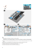
Steps 1. Disconnect the camera cable from the connector (CAM1) on the system board. 2. Disconnect the power-button cable from the connector (PWR1) on the system board. 3. Peel the tapes that secure the camera cable to the palm-rest and keyboard assembly. 4. Open the latch and disconnect the display cable from the connector (LCD1) on the system board. 5. Open the latch and disconnect the keyboard-controller cable from the connector (KBBL2) on the system board. 6. Open the latch and disconnect the touchpad cable from the connector (TPAD1) on the system board. 7. Disconnect the touchpad-LED cable from the connector (TPADLED1) on the system board. 8. Disconnect the speaker cable from the connector (SPK1) on the audio board. 9. Remove the two screws (M2x3) that secure the I/O board to the palm rest and keyboard assembly. 10. Remove the four screws (M2x3) that secure the system board to the palm rest and keyboard assembly. 11. Remove the two screws (M2x3) that secure the audio board to the palm rest and keyboard assembly. 12. After performing all the above steps, you are left with the system-board assembly. 13. Lift the system-board assembly from the palm rest and keyboard assembly and turn it over. 14. Remove the I/O board. 15. Remove the audio board. Installing the system board CAUTION: The information in this installation section is intended for authorized service technicians only. Prerequisites If you are replacing a component, remove the existing component before performing the installation process. 73
-
 1
1 -
2
-
3
-
4
-
5
-
6
-
7
-
8
-
9
-
10
-
11
-
12
-
13
-
14
-
15
-
16
-
17
-
18
-
19
-
20
-
21
-
22
-
23
-
24
-
25
-
26
-
27
-
28
-
29
-
30
-
31
-
32
-
33
-
34
-
35
-
36
-
37
-
38
-
39
-
40
-
41
-
42
-
43
-
44
-
45
-
46
-
47
-
48
-
49
-
50
-
51
-
52
-
53
-
54
-
55
-
56
-
57
-
58
-
59
-
60
-
61
-
62
-
63
-
64
-
65
-
66
-
67
-
 68
68 -
 69
69 -
 70
70 -
 71
71 -
 72
72 -
 73
73 -
 74
74 -
 75
75 -
 76
76 -
 77
77 -
 78
78 -
79
-
80
-
81
-
82
-
83
-
84
-
85
-
86
-
87
-
88
-
89
-
90
-
91
-
92
-
93
-
94
-
95
-
96
-
97
-
98
-
99
-
100
-
101
-
102
-
103
-
104
-
105
-
106
-
107
-
108
-
109
-
110
 |
 |
