Dell Alienware m15 R2 Service Manual - Page 22
Steps, NOTE: This step is only applicable to computers shipped with a Tobii eye tracker.
 |
View all Dell Alienware m15 R2 manuals
Add to My Manuals
Save this manual to your list of manuals |
Page 22 highlights
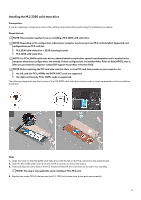
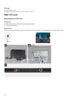
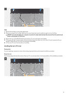
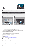
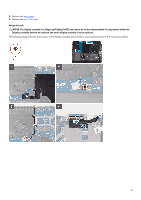
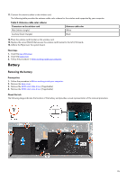
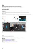
Steps 1. Peel the Mylar covering the system board. 2. Remove the screw (M2x3) that secures the wireless card bracket to the left I/O-board. 3. Lift the wireless card bracket off the left I/O-board. 4. Disconnect the antenna cables from the wireless card. 5. Peel the tapes securing the antenna cables to system board and left fan. 6. Remove the antenna cables from the routing guides on the left fan and system board. 7. Lift the latch and disconnect the display cable from the connector on the system board. 8. Disconnect the G-sensor cable from the connector on the system board. 9. Disconnect the Tobii eye tracker cable from the connector on the system board. NOTE: This step is only applicable to computers shipped with a Tobii eye tracker. 10. Place the computer face up. 11. Remove the following cables from the routing guides on the palm-rest assembly. • Display cable • G-sensor cable • Tobii eye tracker cable • Antenna cables 12. Remove the six screws (M2.5x5) securing the display assembly to the palm-rest assembly. 22
-
 1
1 -
2
-
3
-
4
-
5
-
6
-
7
-
8
-
9
-
10
-
11
-
12
-
13
-
14
-
15
-
16
-
 17
17 -
 18
18 -
 19
19 -
 20
20 -
 21
21 -
 22
22 -
 23
23 -
 24
24 -
 25
25 -
 26
26 -
 27
27 -
28
-
29
-
30
-
31
-
32
-
33
-
34
-
35
-
36
-
37
-
38
-
39
-
40
-
41
-
42
-
43
-
44
-
45
-
46
-
47
-
48
-
49
-
50
-
51
-
52
-
53
-
54
-
55
-
56
-
57
-
58
-
59
-
60
-
61
-
62
-
63
-
64
-
65
-
66
-
67
-
68
-
69
-
70
 |
 |
