Dell Alienware m15 R2 Service Manual - Page 9
Base cover, Removing the base cover
 |
View all Dell Alienware m15 R2 manuals
Add to My Manuals
Save this manual to your list of manuals |
Page 9 highlights
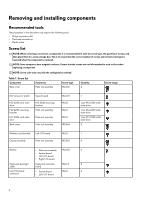
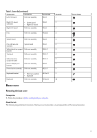
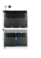
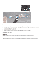
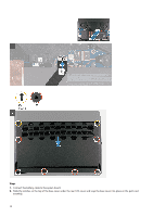
Table 1. Screw list(continued) Component Secured to Left I/O-board Palm-rest assembly Right I/O-board connector Right I/O-board • System board • Right I/O-board Palm-rest assembly Fans Palm-rest assembly Screw type M2x3 M2x3 M2x3 M2.5x5 Quantity 1 2 2 5 Screw image System board Palm-rest assembly M2x3 4 Fan and heat-sink assembly System board M2x3 6 Solid-state drive support Palm-rest assembly M2x1.9 2 bracket Touchpad Palm-rest assembly M2x1.9 4 Solid-state drive Palm-rest assembly M2x1.9 2 support-bracket Power-adapter port Palm-rest assembly M2x3 2 bracket Power-button assembly Palm-rest assembly M2x1.9 3 Keyboard bracket • Palm-rest assembly M1.2x2.1 9 • Keyboard Keyboard Palm-rest assembly M1.2x1.6 33 Base cover Removing the base cover Prerequisites 1. Follow the procedure in Before working inside your computer. About this task The following image indicates the location of the base cover and provides a visual representation of the removal procedure. 9
-
 1
1 -
2
-
3
-
 4
4 -
 5
5 -
 6
6 -
 7
7 -
 8
8 -
 9
9 -
 10
10 -
 11
11 -
 12
12 -
 13
13 -
 14
14 -
15
-
16
-
17
-
18
-
19
-
20
-
21
-
22
-
23
-
24
-
25
-
26
-
27
-
28
-
29
-
30
-
31
-
32
-
33
-
34
-
35
-
36
-
37
-
38
-
39
-
40
-
41
-
42
-
43
-
44
-
45
-
46
-
47
-
48
-
49
-
50
-
51
-
52
-
53
-
54
-
55
-
56
-
57
-
58
-
59
-
60
-
61
-
62
-
63
-
64
-
65
-
66
-
67
-
68
-
69
-
70
 |
 |
