Dell Alienware m15 R2 Service Manual - Page 44
Fan and heat-sink assembly, Removing the fan and heat-sink assembly
 |
View all Dell Alienware m15 R2 manuals
Add to My Manuals
Save this manual to your list of manuals |
Page 44 highlights
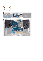
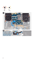
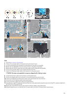
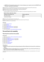
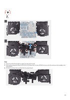
NOTE: The I/O-board cable is polarity sensitive. To prevent damage to your computer ensure that the MB UMT end of the cable is connected to the system board. 16. Replace the two screws (M2x3) that secure the left I/O-board cable to the left I/O-board and the system board. 17. Route the antenna cables to the routing guides on the left fan and system board. 18. Adhere the tapes that secure the antenna cables to system board and left fan. 19. Connect the antenna cables to the wireless card. The following table provides the antenna-cable color scheme for the wireless card supported by your computer. Table 4. Antenna-cable color scheme Connectors on the wireless card Main (white triangle) Antenna-cable color White Auxiliary (black triangle) Black 20.Place the wireless card bracket on the wireless card. 21. Replace the screw (M2x3) that secures the wireless card bracket to the left I/O-board. 22.Adhere the Mylar over the system board. Next steps 1. Install the right I/O-board. 2. Install the battery. 3. Install the rear I/O-cover. 4. Install the 2230 solid-state drive. (if applicable) 5. Install the 2280 solid-state drive. (if applicable) 6. Install the base cover. 7. Follow the procedure in After working inside your computer. Fan and heat-sink assembly Removing the fan and heat-sink assembly Prerequisites 1. Follow the procedure in Before working inside your computer. 2. Remove the base cover. 3. Remove the 2230 solid-state drive. (if applicable) 4. Remove the 2280 solid-state drive. (if applicable) 5. Remove the rear I/O-cover. 6. Remove the battery. 7. Remove the right I/O-board. 8. Remove the system board. About this task NOTE: The heat sink may become hot during normal operation. Allow sufficient time for the heat sink to cool before you touch it. CAUTION: For maximum cooling of the processor, do not touch the heat transfer areas on the heat sink. The oils in your skin can reduce the heat transfer capability of the thermal grease. The following image indicates the location of the fan and heat-sink assembly and provides a visual representation of the removal procedure. 44
-
 1
1 -
2
-
3
-
4
-
5
-
6
-
7
-
8
-
9
-
10
-
11
-
12
-
13
-
14
-
15
-
16
-
17
-
18
-
19
-
20
-
21
-
22
-
23
-
24
-
25
-
26
-
27
-
28
-
29
-
30
-
31
-
32
-
33
-
34
-
35
-
36
-
37
-
38
-
 39
39 -
 40
40 -
 41
41 -
 42
42 -
 43
43 -
 44
44 -
 45
45 -
 46
46 -
 47
47 -
 48
48 -
 49
49 -
50
-
51
-
52
-
53
-
54
-
55
-
56
-
57
-
58
-
59
-
60
-
61
-
62
-
63
-
64
-
65
-
66
-
67
-
68
-
69
-
70
 |
 |
