Dell Alienware m15 R2 Service Manual - Page 34
Installing the right I/O-board
 |
View all Dell Alienware m15 R2 manuals
Add to My Manuals
Save this manual to your list of manuals |
Page 34 highlights
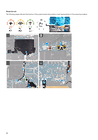
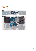
Steps 1. Remove the two screws (M2x3) that secure the right I/O-board cable connecting the right I/O-board and the system board. 2. Lift the right I/O-board cable off the right I/O-board and system board. 3. Disconnect the speaker cable from the right I/O-board. 4. Peel the tape securing the coin-cell battery cable to the right I/O-board. 5. Remove the two screws (M2x3) that secure the right I/O-board to the palm-rest assembly. 6. Lift the right I/O-board off the palm-rest assembly. Installing the right I/O-board Prerequisites If you are replacing a component, remove the existing component before performing the installation procedure. About this task The following image indicates the location of the right I/O-board and provides a visual representation of the installation procedure. 34
-
 1
1 -
2
-
3
-
4
-
5
-
6
-
7
-
8
-
9
-
10
-
11
-
12
-
13
-
14
-
15
-
16
-
17
-
18
-
19
-
20
-
21
-
22
-
23
-
24
-
25
-
26
-
27
-
28
-
 29
29 -
 30
30 -
 31
31 -
 32
32 -
 33
33 -
 34
34 -
 35
35 -
 36
36 -
 37
37 -
 38
38 -
 39
39 -
40
-
41
-
42
-
43
-
44
-
45
-
46
-
47
-
48
-
49
-
50
-
51
-
52
-
53
-
54
-
55
-
56
-
57
-
58
-
59
-
60
-
61
-
62
-
63
-
64
-
65
-
66
-
67
-
68
-
69
-
70
 |
 |
