Dell Alienware m15 R2 Service Manual - Page 33
Right I/O-board, Removing the right I/O-board
 |
View all Dell Alienware m15 R2 manuals
Add to My Manuals
Save this manual to your list of manuals |
Page 33 highlights
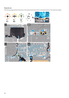
3. Connect the power-button assembly-cable to the left I/O-board and close the latch. 4. Connect the antenna cables to the wireless card. The following table provides the antenna-cable color scheme for the wireless card supported by your computer. Table 3. Antenna-cable color scheme Connectors on the wireless card Main (white triangle) Antenna-cable color White Auxiliary (black triangle) Black 5. Using the alignment pins, connect the left I/O-board cable on the left I/O-board and the system board. NOTE: The I/O-board cable is polarity sensitive. To prevent damage to your computer ensure that the MB UMT end of the cable is connected to the system board. 6. Replace the two screws (M2x3) that secure the left I/O-board cable to the left I/O-board and the system board. 7. Place the wireless-card bracket on the wireless card . 8. Replace the screw (M2x3) that secures the wireless-card bracket to the left I/O-board. 9. Adhere the Mylar over the system board and left I/O-board. Next steps 1. Install the battery. 2. Install the 2230 solid-state drive. (if applicable) 3. Install the 2280 solid-state drive. (if applicable) 4. Install the base cover. 5. Follow the procedure in After working inside your computer. Right I/O-board Removing the right I/O-board Prerequisites 1. Follow the procedure in Before working inside your computer. 2. Remove the base cover. 3. Remove the 2230 solid-state drive. (if applicable) 4. Remove the 2280 solid-state drive. (if applicable) 5. Remove the battery. About this task The following image indicates the location of the right I/O-board and provides a visual representation of the removal procedure. 33
-
 1
1 -
2
-
3
-
4
-
5
-
6
-
7
-
8
-
9
-
10
-
11
-
12
-
13
-
14
-
15
-
16
-
17
-
18
-
19
-
20
-
21
-
22
-
23
-
24
-
25
-
26
-
27
-
 28
28 -
 29
29 -
 30
30 -
 31
31 -
 32
32 -
 33
33 -
 34
34 -
 35
35 -
 36
36 -
 37
37 -
 38
38 -
39
-
40
-
41
-
42
-
43
-
44
-
45
-
46
-
47
-
48
-
49
-
50
-
51
-
52
-
53
-
54
-
55
-
56
-
57
-
58
-
59
-
60
-
61
-
62
-
63
-
64
-
65
-
66
-
67
-
68
-
69
-
70
 |
 |
