Epson EX-1000 User Manual - Page 162
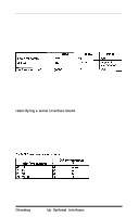
Lift the upper case to release the hinges at the rear edge, then lift - replacement cable
 |
View all Epson EX-1000 manuals
Add to My Manuals
Save this manual to your list of manuals |
Page 162 highlights
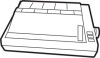
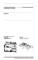
6. With the printer facing you, unclip the left side of the control panel and lift it up slightly to release it from the case (Figure F-2). 7. At each side of the front panel there is a retaining clip, as shown in Figure F-3. One is reached through the control panel opening. Reach behind the cable and gently press the two clips to release the front edge of the upper case. 8. Tilt the upper case up and slip the control panel through the opening as shown in Figure F-4, being careful not to strain the connector linked to the control panel. 9. Lift the upper case to release the hinges at the rear edge, then lift it away from the printer After you have removed the case, you can then follow the directions in the next section on inserting the interface board. After you have inserted the board, you replace the case by reversing steps 2 to 9. Choosing and Setting Up Optional Interfaces F-5
-
 1
1 -
2
-
3
-
4
-
5
-
6
-
7
-
8
-
9
-
10
-
11
-
12
-
13
-
14
-
15
-
16
-
17
-
18
-
19
-
20
-
21
-
22
-
23
-
24
-
25
-
26
-
27
-
28
-
29
-
30
-
31
-
32
-
33
-
34
-
35
-
36
-
37
-
38
-
39
-
40
-
41
-
42
-
43
-
44
-
45
-
46
-
47
-
48
-
49
-
50
-
51
-
52
-
53
-
54
-
55
-
56
-
57
-
58
-
59
-
60
-
61
-
62
-
63
-
64
-
65
-
66
-
67
-
68
-
69
-
70
-
71
-
72
-
73
-
74
-
75
-
76
-
77
-
78
-
79
-
80
-
81
-
82
-
83
-
84
-
85
-
86
-
87
-
88
-
89
-
90
-
91
-
92
-
93
-
94
-
95
-
96
-
97
-
98
-
99
-
100
-
101
-
102
-
103
-
104
-
105
-
106
-
107
-
108
-
109
-
110
-
111
-
112
-
113
-
114
-
115
-
116
-
117
-
118
-
119
-
120
-
121
-
122
-
123
-
124
-
125
-
126
-
127
-
128
-
129
-
130
-
131
-
132
-
133
-
134
-
135
-
136
-
137
-
138
-
139
-
140
-
141
-
142
-
143
-
144
-
145
-
146
-
147
-
148
-
149
-
150
-
151
-
152
-
153
-
154
-
155
-
156
-
 157
157 -
 158
158 -
 159
159 -
 160
160 -
 161
161 -
 162
162 -
 163
163 -
 164
164 -
 165
165 -
 166
166 -
 167
167 -
168
-
169
-
170
-
171
-
172
-
173
-
174
-
175
-
176
-
177
-
178
-
179
-
180
-
181
-
182
-
183
-
184
-
185
-
186
-
187
-
188
-
189
-
190
-
191
-
192
 |
 |
