Gateway E-9525R Gateway E-9525R Server User Guide
Gateway E-9525R Manual
 |
View all Gateway E-9525R manuals
Add to My Manuals
Save this manual to your list of manuals |
Gateway E-9525R manual content summary:
- Gateway E-9525R | Gateway E-9525R Server User Guide - Page 1
E-9525R Server USERGUIDE ® - Gateway E-9525R | Gateway E-9525R Server User Guide - Page 2
- Gateway E-9525R | Gateway E-9525R Server User Guide - Page 3
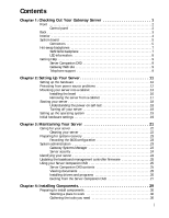
7 SAS/SATA backplane 7 LED information 8 Getting Help 9 Server Companion DVD 9 Gateway Web site 9 Telephone support 9 Chapter 2: Setting Up Your Server 11 Setting up the hardware 12 Protecting from power source problems 12 Mounting your server into a cabinet 13 Installing the bezel 16 - Gateway E-9525R | Gateway E-9525R Server User Guide - Page 4
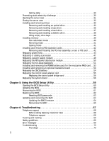
server case 31 Closing the server case 32 Installing and removing drives 33 Removing and installing an optical drive 33 Removing and installing a tape drive 35 Removing and installing a hard drive 37 Removing and installing a diskette drive 38 Filling empty drive bays 39 Installing memory - Gateway E-9525R | Gateway E-9525R Server User Guide - Page 5
www.gateway.com Battery replacement 73 Beep codes 74 LED information 75 Diagnostic LEDs 76 BIOS 81 Optical drive 81 Expansion cards 82 Hard drive 82 Internet 83 Keyboard 83 Memory 83 Monitor 83 Power 84 Processor 84 Appendix A: Server Specifications 85 System specifications 86 System - Gateway E-9525R | Gateway E-9525R Server User Guide - Page 6
Contents iv - Gateway E-9525R | Gateway E-9525R Server User Guide - Page 7
CHAPTER 1 Checking Out Your Gateway Server • Front • Back • Interior • System board • Hot-swap backplanes • Getting Help 1 - Gateway E-9525R | Gateway E-9525R Server User Guide - Page 8
Front CHAPTER 1: Checking Out Your Gateway Server Hard drives Hard drive tray LEDs Control panel Optical drive Control panel # Feature 1 Power button 2 Power LED 3 Reset button 4 NMI button 5 System fault LED 6 NIC status LED 2 # Feature 7 SMIL module plug 8 VGA connector 9 - Gateway E-9525R | Gateway E-9525R Server User Guide - Page 9
Back www.gateway.com Dual NIC connectors PS/2 Keyboard port VGA port Serial port Server management port PS/2 Mouse port ID LED Dual USB ports SAS JBOD connector (optional) Power supply AC power connector 3 - Gateway E-9525R | Gateway E-9525R Server User Guide - Page 10
CHAPTER 1: Checking Out Your Gateway Server # Feature # Feature 1 System board 9 Control panel adapter card 2 Fan duct 10 SAS/SATA backplane 3 System fans 11 System fans 4 Tape drive (optional) 12 System fans 5 Slimline DVD/CD-RW combo drive or 13 RPS power distribution - Gateway E-9525R | Gateway E-9525R Server User Guide - Page 11
System board Connectors www.gateway.com 37 36 35 34 33 32 31 30 29 28 # Feature 1 Rear dual USB Port (J35) 2 Serial port (J31) 3 ID LED (CR16) 4 VGA port ( - Gateway E-9525R | Gateway E-9525R Server User Guide - Page 12
CHAPTER 1: Checking Out Your Gateway Server # Feature 5 PS/2 mouse port (J15) 6 PS/2 keyboard port (J6) 7 Server management port (J59) 8 Dual NIC connector (RJ-45) (J14) 9 PCI-E expansion slot (J4) 10 PCI-X/PCI-E expansion slot (J9) 11 Battery (B1) 12 System configuration - Gateway E-9525R | Gateway E-9525R Server User Guide - Page 13
www.gateway.com Hot-swap backplanes SAS/SATA backplane # Feature 1 SAS/SATA hard drive connector 0 2 SAS/SATA hard drive connector 1 3 SAS/SATA hard drive connector 2 4 SAS/SATA hard drive connector 3 # Feature 5 SAS/SATA hard drive connector 4 6 SAS/SATA hard drive connector 5 7 - Gateway E-9525R | Gateway E-9525R Server User Guide - Page 14
On = Server identification identification back of system (front) enabled board Blue (back) System Fault Visible fault warning Control panel Red Off = System normal Blinking = Non-critical system fault On = Critical system fault (system needs to be shut down and serviced) Hard drive tray - Gateway E-9525R | Gateway E-9525R Server User Guide - Page 15
you use your server. Visit the Gateway Web site at support.gateway.com for: • Technical documentation and product guides • Technical tips and support • Updated hardware drivers • Order status • Frequently asked questions (FAQs) Telephone support You can access a wide range of services through your - Gateway E-9525R | Gateway E-9525R Server User Guide - Page 16
CHAPTER 1: Checking Out Your Gateway Server 10 - Gateway E-9525R | Gateway E-9525R Server User Guide - Page 17
CHAPTER 2 Setting Up Your Server • Setting up the hardware • Protecting from power source problems • Mounting your server into a cabinet • Starting your server • Setting up the operating system • Initial hardware settings 11 - Gateway E-9525R | Gateway E-9525R Server User Guide - Page 18
data on both diskettes and hard drives. Even a telephone placed too close to the server may cause interference. Important Keep the server boxes and packing material in case you need to ship the server. Protecting from power source problems Surge protectors, line conditioners, and uninterruptible - Gateway E-9525R | Gateway E-9525R Server User Guide - Page 19
.gateway.com. Mounting your server into a cabinet Caution Before attaching cabinet accessories, make sure that the server is server, refer to the instructions included in the kit. To mount your server in a cabinet: 1 Align the slots in the front server rails with the studs on the side of the server - Gateway E-9525R | Gateway E-9525R Server User Guide - Page 20
the rail forward until it stops. Locking screw (installed) Back server rail Stud (installed) Stud 4 Align the locking screw holes in the rails with the threaded screw holes in the server, then install one locking screw through the each back server rail. 5 Attach one mounting nut to each of the - Gateway E-9525R | Gateway E-9525R Server User Guide - Page 21
.gateway.com 6 Attach one mounting nut to each of the two back cabinet posts where you plan to install the server. Back cabinet post Mounting nut Hinged back rail mounting bracket Warning You must support the server while installing or removing the front and back mounting screws. If the server - Gateway E-9525R | Gateway E-9525R Server User Guide - Page 22
mounting nuts, then secure the front in place with two mounting screws (one on each side). Installing the bezel To install the bezel: 1 With the server pulled out from the cabinet, align the holes in the handle with the small holes in the mounting brackets on the front side of the - Gateway E-9525R | Gateway E-9525R Server User Guide - Page 23
www.gateway.com Back view Handle Mounting screw Front view Mounting bracket Mounting required to support the front of the server. You must support the server while removing the front screws and while sliding the server off the cabinet rails. If the server is not supported, damage to the server or - Gateway E-9525R | Gateway E-9525R Server User Guide - Page 24
on your server, the power-on self-test (POST) routine checks the server memory and components. If POST finds any problems, the server displays error messages. Write down any error messages that you see, then see "Error messages" on page 69 and "Beep codes" on page 74 for troubleshooting information - Gateway E-9525R | Gateway E-9525R Server User Guide - Page 25
for your specific network. If you are installing an operating system because it was not already installed by Gateway, see the appropriate installation guide for instructions. Initial hardware settings Your server comes from the manufacturer with the correct initial hardware settings to operate your - Gateway E-9525R | Gateway E-9525R Server User Guide - Page 26
CHAPTER 2: Setting Up Your Server 20 - Gateway E-9525R | Gateway E-9525R Server User Guide - Page 27
CHAPTER 3 Maintaining Your Server • Caring for your server • Preparing for system recovery • System administration • Identifying your server • Updating the baseboard management controller firmware • Using your Server Companion DVD 21 - Gateway E-9525R | Gateway E-9525R Server User Guide - Page 28
can of air with a narrow, straw-like extension • Isopropyl alcohol • Cotton swabs • A tape drive cleaning cartridge (if a tape drive is installed) • A CD drive cleaning kit Cleaning tips Warning When you shut down your server, the power turns off, but some electrical current still flows through your - Gateway E-9525R | Gateway E-9525R Server User Guide - Page 29
are triggered by certain events or conditions. For more information, refer to the Gateway Baseboard Management Controller (BMC) User Guide at http://support.gateway.com/support/default.asp# (by selecting this server from the list). You can also find additional information in the program's online - Gateway E-9525R | Gateway E-9525R Server User Guide - Page 30
Setup utility. To remove a BIOS security password: Tip Passwords can also be cleared using jumpers on the system board. For instructions, see "Resetting BIOS passwords" on page 63. 1 Restart your server, then press F2 at any time after you see the LEDs on your keyboard flash or turn off. The BIOS - Gateway E-9525R | Gateway E-9525R Server User Guide - Page 31
BMC firmware zip file from support.gateway.com. 2 Read the release notes for the firmware update. 3 Follow the instructions on the Web site or in Insert the Server Companion DVD into the DVD drive on a computer running the Windows operating system. The Gateway Application and Driver Recovery window - Gateway E-9525R | Gateway E-9525R Server User Guide - Page 32
on-screen instructions. To access the files manually, open the Drivers folder on the Server Companion DVD, then open the appropriate subfolder. To extract drivers and programs to diskettes: 1 Insert the Server Companion DVD into your server's DVD drive. The Gateway Application and Driver Recovery - Gateway E-9525R | Gateway E-9525R Server User Guide - Page 33
the DVD drive. 2 Restart your server. A message appears asking you to select an option. 3 Press any key to boot from the DVD. The Gateway Options Main Menu appears. 4 Follow any on-screen instructions. You can use the options in this menu to reformat your hard drive, create mass-storage driver disks - Gateway E-9525R | Gateway E-9525R Server User Guide - Page 34
CHAPTER 3: Maintaining Your Server 28 - Gateway E-9525R | Gateway E-9525R Server User Guide - Page 35
4 Installing Components • Preparing to install components • Preventing static electricity discharge • Opening the server case • Closing the server case • Installing and removing drives • Installing memory • Installing and removing PCI expansion cards • Replacing system fans • Replacing or adding - Gateway E-9525R | Gateway E-9525R Server User Guide - Page 36
• Has a stable surface on which to set your server. • Has enough room to place all of your server parts. • Is near a grounded outlet so you can test your server after installation. • Is near a telephone (in case you need help from Gateway Customer Care). The telephone must be directly connected to - Gateway E-9525R | Gateway E-9525R Server User Guide - Page 37
the front screws and while sliding the server off the cabinet rails. If the server is not supported, damage to the server or injury may result. 3 If the server is mounted in a cabinet, remove the server from the cabinet. For instructions, see "Removing the server from a cabinet" on page 17. 4 Place - Gateway E-9525R | Gateway E-9525R Server User Guide - Page 38
you close the case. 2 Place the top cover (1) on the server, then slide it forward until it clicks into place. Important The hard drive carriers shown in these illustrations may look different than the actual hard drive carriers in your server. 3 Replace the screw (2) to hold the top cover in place - Gateway E-9525R | Gateway E-9525R Server User Guide - Page 39
pulling it from the chassis. 3 Follow the instructions in "Opening the server case" on page 31. 4 Remove the large fan cage by following the instructions in "Replacing system fans" on page 44. 5 Disconnect the 44-pin optical drive cable from the optical drive interface board. 6 Loosen the thumbscrew - Gateway E-9525R | Gateway E-9525R Server User Guide - Page 40
board to the back of the new optical drive. 11 Align the optical drive with the two clips on the left side of the optical drive tray, then press the optical drive into place in the tray. 12 Insert the optical drive tray into the bay in the media cage until it clicks into place. 13 - Gateway E-9525R | Gateway E-9525R Server User Guide - Page 41
previously loosened. 15 Attach the 44-pin optical drive cable to the back of the optical drive interface board. 16 Reinstall the large fan cage by following the instructions in "Replacing system fans" on page 44. 17 Follow the instructions in "Closing the server case" on page 32. 18 Reinstall the - Gateway E-9525R | Gateway E-9525R Server User Guide - Page 42
loosened. 13 Connect the data and power cables to the back of the tape drive. 14 Reinstall the large fan cage by following the instructions in "Replacing system fans" on page 44. 15 Follow the instructions in "Closing the server case" on page 32. 16 Reinstall the bezel, if required, by snapping it - Gateway E-9525R | Gateway E-9525R Server User Guide - Page 43
to add or replace a hard drive in a hot-swap bay. Your server supports as many as six 1-inch high, 3.5-inch hot-swap SATA and SATA II hard drives or six 1-inch high, 3.5-inch hot-swap SAS hard drives. You can purchase additional drives through your Gateway Sales or Customer Care representative. To - Gateway E-9525R | Gateway E-9525R Server User Guide - Page 44
remove it by pulling it from the chassis. 3 Follow the instructions in "Opening the server case" on page 31. 4 Disconnect the USB cable from the diskette drive. 5 Lift the blue locking tab on the back of the diskette drive tray, then push the drive tray out the front of the media cage. Blue locking - Gateway E-9525R | Gateway E-9525R Server User Guide - Page 45
bezel by snapping it into place on the front of the server. Empty drive carriers for unused drive bays are included with your server. Installing memory Caution Use only 667 MHz Fully-Buffered (FB-DIMM) memory modules. Your server supports eight 667 MHz fully-buffered DIMMs (FB-DIMMs) to provide up - Gateway E-9525R | Gateway E-9525R Server User Guide - Page 46
CHAPTER 4: Installing Components The BIOS configures the memory controller to run in non-redundant, mirroring, and GB DIMM7 512 MB 1 GB 2 GB 4 GB 512 MB 1 GB 2 GB 4 GB DIMM8 512 MB 1 GB 2 GB 4 GB Total Usable Memory 512 MB 1 GB 2 GB 4 GB 1 GB 2 GB 4 GB 8 GB 2 GB 4 GB 8 GB 16 GB 2 GB 4 GB 8 - Gateway E-9525R | Gateway E-9525R Server User Guide - Page 47
www.gateway.com Mirroring mode: DIMM Installation Options - Mirroring Mode DIMM DIMM1 DIMM2 DIMM3 DIMM4 4 512 . To install or replace memory: 1 Follow the instructions in "Preventing static electricity discharge" on page 30. Make sure that you turn off the server, then unplug the power cord - Gateway E-9525R | Gateway E-9525R Server User Guide - Page 48
memory slot should secure the memory module automatically. 5 Follow the instructions in "Closing the server case" on page 32. 6 Turn on the server and open the BIOS setup utility. Verify the System Memory the riser card. The PCI-E expansion slot can support two PCI-E x8 slots with x4 speed using the - Gateway E-9525R | Gateway E-9525R Server User Guide - Page 49
www.gateway.com 4 Push the release clips (1) in the direction shown in the illustration, then lift the assembly (2) out of the chassis. Caution Do not touch the - Gateway E-9525R | Gateway E-9525R Server User Guide - Page 50
instructions in "Closing the server case" on page 32. 14 See the card's documentation for software installation instructions. Replacing system fans This server fans maintain the ideal temperature for the system board, backplane, and disk drives. If one fan fails, the speed of the other fans will - Gateway E-9525R | Gateway E-9525R Server User Guide - Page 51
www.gateway.com 3 Determine which fan group needs to be replaced by noting which fans fan cage and press down the locking handle to secure the fan group in place. 6 Follow the instructions in "Closing the server case" on page 32. To replace the system fan and fan cage assembly: Important Both system - Gateway E-9525R | Gateway E-9525R Server User Guide - Page 52
chassis (3), then push it in the direction of the arrow to lock it into place (4). 9 Replace the fan duct into the chassis. 10 Follow the instructions in "Closing the server case" on page 32. 46 - Gateway E-9525R | Gateway E-9525R Server User Guide - Page 53
www.gateway.com Replacing or adding a processor Warning Processors and heat sinks may be page 30. Make sure that you turn off the server, then unplug the power cord(s) and all other cables connected to the server. 3 Follow the instructions in "Opening the server case" on page 31. 4 Push down, then - Gateway E-9525R | Gateway E-9525R Server User Guide - Page 54
CHAPTER 4: Installing Components 6 Unlock the load lever (1) and lift it up, then open the load plate (2) to release the processor. 7 Lift the processor (3) out of the socket and place it in a static-free bag or case for storage. Caution The processor only fits the socket when oriented as indicated. - Gateway E-9525R | Gateway E-9525R Server User Guide - Page 55
sink socket. 12 Follow the instructions in "Closing the server case" on page 32. Replacing a power supply module Caution The power supplies in this server contain no user-serviceable parts. Only a qualified computer technician should service the power supplies. Your server comes with 3-wire AC power - Gateway E-9525R | Gateway E-9525R Server User Guide - Page 56
, then unplug the power cord(s) and all other cables connected to the server. 2 Follow the instructions in "Opening the server case" on page 31. 3 Remove the power supply modules by following the instructions in "Replacing a power supply module" on page 49. 4 Disconnect the main power, CPU power - Gateway E-9525R | Gateway E-9525R Server User Guide - Page 57
www.gateway.com 5 Push down the release bar (1). server. 3 Follow the instructions in "Opening the server case" on page 31. 4 Remove all of the hot-swap drive carriers from the server and make note of which bay you remove each drive from. For instructions, see "Removing and installing a hard drive - Gateway E-9525R | Gateway E-9525R Server User Guide - Page 58
CHAPTER 4: Installing Components 5 Remove the fan duct and system fans by following the instructions in "Replacing system fans" on page 44. 6 Disconnect all cables from the backplane. 7 Pull the backplane bracket and backplane (1) out of the chassis. Caution Pressing - Gateway E-9525R | Gateway E-9525R Server User Guide - Page 59
www.gateway.com 11 Slide the backplane to the right, locking it into 32. 16 Reinstall the hot-swap drives back into the server. Make sure that you install the drives into the same bays you removed them from in Step 4. For instructions see "Removing and installing a hard drive" on page 37. 17 Replace - Gateway E-9525R | Gateway E-9525R Server User Guide - Page 60
CHAPTER 4: Installing Components 5 Follow the instructions in "Closing the server case" on page 32. Installing and removing an optional mezzanine board For information on installing and removing the optional mezzanine board, refer to the Mezzanine Board User Guide. Replacing the CMOS battery Warning - Gateway E-9525R | Gateway E-9525R Server User Guide - Page 61
to the server. 2 Follow the instructions in "Opening the server case" on page 31. 3 Remove the fan duct and system fans by following the instructions in "Replacing system fans" on page 44. 4 Remove the media cage by following the instructions in "Removing and installing an optical drive" on page - Gateway E-9525R | Gateway E-9525R Server User Guide - Page 62
chassis. 10 Insert the media cage into the assembly bay in the chassis. 11 Secure the assembly by drives and the control panel bridge card. 13 Reinstall the fan duct and system fans by following the instructions in "Replacing system fans" on page 44. 14 Follow the instructions in "Closing the server - Gateway E-9525R | Gateway E-9525R Server User Guide - Page 63
www.gateway.com 4 Remove the fan duct and system fan cage by following the instructions in "Replacing system fans" on page 44. 5 Remove the memory modules by following the instructions in "Installing memory" on page 39. 6 Remove the heatsinks and processors by following the instructions in " - Gateway E-9525R | Gateway E-9525R Server User Guide - Page 64
a processor" on page 47. 17 Reinstall the PCI riser assembly by following the instructions in "Installing and removing PCI expansion cards" on page 42. 18 Follow the instructions in "Closing the server case" on page 32. 19 Restart your server, then press F2 at any time after you see the LEDs on your - Gateway E-9525R | Gateway E-9525R Server User Guide - Page 65
CHAPTER 5 Using the BIOS Setup Utility • Opening the BIOS Setup utility • Updating the BIOS • Recovering the BIOS • Resetting the BIOS • Updating and recovering the BMC 59 - Gateway E-9525R | Gateway E-9525R Server User Guide - Page 66
this guide's appendix for "BIOS Settings" on page 93. To open the BIOS Setup utility: 1 Restart your server, then support.gateway.com. 5 Follow the instructions on the Web site or the readme.txt file in the downloaded zip file to update the BIOS. 6 After you have updated the BIOS, restart your server - Gateway E-9525R | Gateway E-9525R Server User Guide - Page 67
you see a message on the screen. 3 Remove the diskette, the CD or DVD, or the bootable USB "disk-on-key." 4 Restart the server. The old BIOS is recovered. To manually recover the BIOS: 1 Follow the instructions in "Preventing static electricity discharge" on page 30. Make sure that you turn off the - Gateway E-9525R | Gateway E-9525R Server User Guide - Page 68
1 Print the appendix for "BIOS Settings" on page 93 in this guide. 2 Restart your server, then press F2 at any time after you see the LEDs on your turn off the server, then unplug the power cord(s) and all other cables connected to the server. 5 Follow the instructions in "Opening the server case" on - Gateway E-9525R | Gateway E-9525R Server User Guide - Page 69
www.gateway.com 6 Remove the jumper across pins 1-2 of header J3-B, then place the jumper across pins 2-3. 7 Follow the instructions in "Closing the server case" on page 32. 8 Reconnect the power cords and turn on the server. The BIOS is reset. 9 Turn off the server, then disconnect the power cords - Gateway E-9525R | Gateway E-9525R Server User Guide - Page 70
31. 8 Place the jumper back onto pins 1-2. 9 Follow the instructions in "Closing the server case" on page 32. Updating and recovering the BMC Updating the BMC firmware To update the BMC firmware: 1 Download the BMC firmware zip file from support.gateway.com. 2 Read the release notes for the firmware - Gateway E-9525R | Gateway E-9525R Server User Guide - Page 71
www.gateway.com Recovering the BMC If you encounter a problem while you are updating the BMC, such as a the KVM switch. To manually recover the BMC: 1 Follow the instructions in "Preventing static electricity discharge" on page 30. Make sure that you turn off the server, then unplug the power cord - Gateway E-9525R | Gateway E-9525R Server User Guide - Page 72
CHAPTER 5: Using the BIOS Setup Utility 66 - Gateway E-9525R | Gateway E-9525R Server User Guide - Page 73
CHAPTER 6 Troubleshooting • Telephone support • Tutoring and training • Safety guidelines • Error messages • Troubleshooting 67 - Gateway E-9525R | Gateway E-9525R Server User Guide - Page 74
CHAPTER 6: Troubleshooting Telephone support Before calling Gateway Customer Care If you have a technical problem with your server, follow these recommendations before contacting Gateway Customer Care: • Make sure that your server is connected correctly to a grounded AC outlet that is supplying - Gateway E-9525R | Gateway E-9525R Server User Guide - Page 75
. Select from several easy-to-use learning libraries. www.gateway.com/training Safety guidelines While troubleshooting your server, follow these safety guidelines: Warning To avoid bodily injury, do not attempt to troubleshoot your server problem if: - The power cords or plugs are damaged - Liquid - Gateway E-9525R | Gateway E-9525R Server User Guide - Page 76
Troubleshooting Boot messages Boot Failure ... This is a generic message indicating the BIOS could not boot from a particular device. This message is usually followed by other information concerning the device. Invalid Boot Diskette A diskette was found in the drive or removable media drive does not - Gateway E-9525R | Gateway E-9525R Server User Guide - Page 77
gateway.com Secondary Master Drive - ATAPI Incompatible The IDE/ATAPI device configured as Secondary Master failed an ATAPI compatibility test. This message is typically displayed when the BIOS is trying to detect and configure IDE/ATAPI devices in POST. Secondary Slave Drive a problem with system - Gateway E-9525R | Gateway E-9525R Server User Guide - Page 78
Troubleshooting NVRAM or more Static Devices are trying to use the same resource space (usually Memory or I/O). PCI I/O conflict A PCI adapter generated an I/O resource conflict channel 2 of the 8254 timer. This may indicate a problem with system hardware. Interrupt Controller-1 error BIOS POST could - Gateway E-9525R | Gateway E-9525R Server User Guide - Page 79
the exact message before calling Gateway Customer Care. For instructions, see "Telephone support" on page 68. • Restart your server, then open the BIOS Setup utility by pressing and holding F2 while your server restarts. Check your configuration settings. • When diagnosing problems, press the non - Gateway E-9525R | Gateway E-9525R Server User Guide - Page 80
CHAPTER 6: Troubleshooting • Remove the top panel by following the instructions in "Opening the server case" on page 31, then make sure that all cables inside the case are attached securely. Also, make sure that the colored cable edges are - Gateway E-9525R | Gateway E-9525R Server User Guide - Page 81
On - Server identification identification back of system (front) enabled board Blue (back) System Fault Visible fault warning Control panel Red Off - System normal Blinking - Non-critical system fault On - Critical system fault (system needs to be shut down and serviced) Hard drive tray - Gateway E-9525R | Gateway E-9525R Server User Guide - Page 82
This system board provides a set of eight diagnostic (Port 80) LEDs. If you are troubleshooting your system, these LEDs can help you determine where errors are taking place. If you are experiencing problems with your server, open the case and check these LEDs (CR8 to CR15) on the system board, then - Gateway E-9525R | Gateway E-9525R Server User Guide - Page 83
www.gateway.com In determining the code the mouse, to solve the problem. All LEDs are cleared and restored to normal status after the server is power cycled. POST code checkpoints is OK and CMOS checksum is OK. Verify CMOS checksum manually by reading storage area. If the CMOS checksum is bad, - Gateway E-9525R | Gateway E-9525R Server User Guide - Page 84
6: Troubleshooting Check needed. Updates CMOS memory size from memory found in memory test. Allocates memory for Extended BIOS Data Area from base memory. Initialize NUM-LOCK of chipset registers. Build ACPI tables (if ACPI is supported). Program the peripheral parameters. Enable/disable NMI as - Gateway E-9525R | Gateway E-9525R Server User Guide - Page 85
www.gateway.com Check point A2 A4 A7 A8 A9 AA AB AC B1 00 Description Take information. D7 Restore CPUID value back into register. The Bootblock-Runtime interface module is moved to system memory and control is given to it. Determine whether to execute serial flash. D8 The Runtime module is - Gateway E-9525R | Gateway E-9525R Server User Guide - Page 86
CHAPTER 6: Troubleshooting Check point D9 DA Description Store the Uncompressed pointer for future use in PMM. Copying Main BIOS into memory. Leaves all RAM below 1 MB Read-Write, including E000 and F000 shadow areas, but closing SMRAM. Restore CPUID value back into register. Give control to - Gateway E-9525R | Gateway E-9525R Server User Guide - Page 87
an optical drive • Restart your server, then open the BIOS Setup utility by pressing and holding F2 while your server restarts. Make sure that the IDE controllers are enabled. For more information, see "Using the BIOS Setup Utility" on page 59. • Reinstall the device driver. For instructions, see - Gateway E-9525R | Gateway E-9525R Server User Guide - Page 88
. The drive tray opens. • If this problem happens frequently while the server is turned on, the drive may be defective. Expansion cards Your server does not recognize an expansion card • Restart your server. • Make sure that you have installed the necessary software or driver. For instructions, see - Gateway E-9525R | Gateway E-9525R Server User Guide - Page 89
www.gateway.com Internet Keyboard Memory Monitor See also Modem. You cannot connect to the Internet • Make sure that your account with your Internet Service Provider (ISP) is set up correctly. Contact your ISP technical support for help. • Make sure that you do not have a problem with your modem. - Gateway E-9525R | Gateway E-9525R Server User Guide - Page 90
troubleshooting, see "Monitor" on page 83. • If your server to plug the server directly into server and make sure that server, it makes several short beeps • The short beeps indicate the server has encountered some type of error. See "Beep codes" on page 74. Your server server from one processor - Gateway E-9525R | Gateway E-9525R Server User Guide - Page 91
APPENDIX A Server Specifications • System specifications • System board specifications • Environmental specifications • Electronic specifications • Additional specifications 85 - Gateway E-9525R | Gateway E-9525R Server User Guide - Page 92
swap hard drive bays Card sizes Supports three full-length, full-height and two low-profile PCI expansion cards Power supply One 700 W hot-swap, power supply module (standard) Additional 700 W hot-swap redundant power supply module (optional) Operating systems Supports Windows Server 2003 (all - Gateway E-9525R | Gateway E-9525R Server User Guide - Page 93
gateway.com PCIe x8 mezzanine board for SAS HBA and RAID support. ACPI 2.0b compliance Supports: ■ S0 ■ S1 ■ S5 Environmental specifications The following specifications identify maximum environmental conditions. At no time should the server supply Electronic specifications Memory map Address - Gateway E-9525R | Gateway E-9525R Server User Guide - Page 94
APPENDIX A: Server Specifications Interrupts Important If you disable an IDE controller to free the interrupt for that controller, you must physically unplug the IDE cable from the system board. Simply disabling the drive by configuring the BIOS option does not make the interrupt available. The - Gateway E-9525R | Gateway E-9525R Server User Guide - Page 95
www.gateway.com Pin Signal Name 8 Power good 9 Stand by +5 V 10 +12 V 11 +12 V 12 +3.3 V 13 +3.3 V 14 -12 V 15 Ground 16 DC_ON (soft on/off) 17 Ground - Gateway E-9525R | Gateway E-9525R Server User Guide - Page 96
APPENDIX A: Server Specifications Pin Signal Name 3 Blue (analog color signal B) 4 No connection 5 GND 6 GND 7 +5 V 8 GND 9 +5 V 10 GND 11 No connection 12 SDA 13 HSYNC (horizontal sync) 14 - Gateway E-9525R | Gateway E-9525R Server User Guide - Page 97
5 +3.3 V Additional specifications For more information about your server, such as memory size, hard drive size, and processor type, visit Gateway's eSupport page at support.gateway.com. The eSupport page also has links to additional Gateway documentation and detailed specifications for your own - Gateway E-9525R | Gateway E-9525R Server User Guide - Page 98
APPENDIX A: Server Specifications 92 - Gateway E-9525R | Gateway E-9525R Server User Guide - Page 99
APPENDIXB BIOS Settings 93 - Gateway E-9525R | Gateway E-9525R Server User Guide - Page 100
BIOS settings, run the BIOS Setup utility. To view all BIOS settings: 1 Restart your server, then press F2 at any time after you see the LEDs on your keyboard flash or Build date, System ID, Version), Processor (Type, Speed, Count) System Memory (Size) System Time System Date HH:MM:SS DAY MM/DD/YYYY - Gateway E-9525R | Gateway E-9525R Server User Guide - Page 101
BIOS menu www.gateway.com BIOS submenu Memory Configuration IDE Configuration Setting Hyper-Threading Technology Intel Speed Step™ Tech Value Enabled Disabled Auto Disabled Memory Performance Mode Total Memory Capacity Memory Redundancy DIMM 1 DIMM 2 DIMM 3 DIMM 4 DIMM 5 DIMM 6 DIMM 7 DIMM 8 - Gateway E-9525R | Gateway E-9525R Server User Guide - Page 102
96 BIOS menu APPENDIX B: BIOS Settings BIOS submenu Super I/O Configuration Setting Primary IDE Master Primary IDE Slave Secondary IDE Master Secondary IDE Slave Third IDE Master Fourth IDE Master Fourth IDE Slave ACHI Port 0 ACHI Port 1 ACHI Port 2 ACHI Port 3 ACHI Port 4 ACHI Port 5 Hard Disk - Gateway E-9525R | Gateway E-9525R Server User Guide - Page 103
menu www.gateway.com BIOS submenu USB Configuration PCI Configuration Setting Serial Port 1 Address Serial Port 1 IRQ PS/2 Keyboard PS/2 Mouse Value Disabled 3F8 2F8 3E8 2E8 IRQ3 IRQ4 IRQ10 IRQ11 Present Present USB Devices Enabled (List of USB devices detected by BIOS) Legacy USB Support USB - Gateway E-9525R | Gateway E-9525R Server User Guide - Page 104
Num-Lock POST Error Pause Boot Device Priority 1st Boot Device nth Boot Device Hard Disk Drives 1st Drive nth Drive Removable Drive 1st Drive nth Drive CD/DVD Drives 1st Drive nth Drive Value ■ Top PCIe slot Option ROM (enabled or disabled) ■ Bottom PCIe slot Option ROM (enabled or - Gateway E-9525R | Gateway E-9525R Server User Guide - Page 105
BIOS menu Server www.gateway.com BIOS submenu Setting Value Administrator Password (Installed/Not installed) User Reset Switches Inhibit Disabled Enabled NMI Control Disabled Enabled System Management Server Board Part Number Server Board Serial Number NIC 1 MAC Address NIC 2 MAC Address - Gateway E-9525R | Gateway E-9525R Server User Guide - Page 106
Access Serial Port Number (Base address and IRQ) Serial Port Mode Flow Control Redirection After BIOS POST Terminal Type VT-UTF8 Combo Key Support IPMI Configuration Status of BMC BMC Firmware Revision View BMC Event Log Clear BMC System Event Log BMC PEF Status Toggle PEF IOat Restore - Gateway E-9525R | Gateway E-9525R Server User Guide - Page 107
www.gateway.com BIOS menu drive type) Device Device information Vendor Device vendor Size Device size LBA Mode Device LBA mode Block Mode Device block mode PIO Mode Device PIO mode Async DMA Device Async DMA mode Ultra DMA Device Ultra DMA mode S.M.A.R.T. Device S.M.A.R.T. support - Gateway E-9525R | Gateway E-9525R Server User Guide - Page 108
APPENDIX B: BIOS Settings BIOS submenu BIOS 2nd level submenu Setting S.M.A.R.T. 32Bit Data Transfer Value Auto Disabled Enabled Disabled Enabled BIOS submenu USB Configuration BIOS 2nd level submenu USB Mass Storage Device Configuration Setting USB Mass Storage Reset Delay Device #1 Emulation - Gateway E-9525R | Gateway E-9525R Server User Guide - Page 109
APPENDIXC Legal Information 103 - Gateway E-9525R | Gateway E-9525R Server User Guide - Page 110
. See installation instructions for details. service may be required. The telephone company may request that you disconnect the equipment until the problem Gateway Companies, Inc. 610 Gateway Drive, North Sioux City, SD 57049 (605) 232-2000 Fax: (605) 232-2023 Product: ■ Gateway E-9525R Server - Gateway E-9525R | Gateway E-9525R Server User Guide - Page 111
approved by Gateway could void service location. Warning Use of controls or adjustments or performance of procedures other than those specified in this manual may result in hazardous radiation exposure. To prevent exposure to laser beams, do not try to open the enclosure of a CD or DVD drive - Gateway E-9525R | Gateway E-9525R Server User Guide - Page 112
Irvine Center Drive Irvine, CA 92618-2930 USA All Rights Reserved This publication is protected by copyright and all rights are reserved. No part of it may be reproduced or transmitted by any means or in any form, without prior consent in writing from Gateway. The information in this manual has been - Gateway E-9525R | Gateway E-9525R Server User Guide - Page 113
APPENDIXD Safety Information 107 - Gateway E-9525R | Gateway E-9525R Server User Guide - Page 114
follow these instructions to help guard against personal injury and damage to your Gateway system. Your Gateway system is must disconnect both power cords. ■ Unplug the system from the wall outlet and refer servicing to qualified personnel if: ■ The power cord or plug is damaged. ■ Liquid has - Gateway E-9525R | Gateway E-9525R Server User Guide - Page 115
77 DIM code checkpoints 81 DIMM see memory diskette drive connector 5 location 2 display troubleshooting 83 documentation Gateway Web site 9 Server Companion DVD 25 drive bays location 2 drivers installing 25 drives configuring 33 diskette 2 hard drive 2, 37 hot-swap 2, 37 installing 33, 37 - Gateway E-9525R | Gateway E-9525R Server User Guide - Page 116
cleaning 22 troubleshooting 83 L LED information 8, 75 LEDs 2 diagnostic 76 system board 8, 75 line conditioners 12 location drive bays 4 fan module 4 memory slots 12 reset button 2 source problems 12 static electricity 30 surge protectors 12 troubleshooting 84 uninterruptible power supply (UPS - Gateway E-9525R | Gateway E-9525R Server User Guide - Page 117
83 LED information 8, 75 master boot record 82 memory 83 monitor 83 optical drive 81 power 84 power source problems 12 processor 84 safety guidelines 69 technical support 68 telephone support 68 video 83 turning off server 19 turning on server 18 U uninterruptible power supply (UPS) 13 UPS 13 - Gateway E-9525R | Gateway E-9525R Server User Guide - Page 118
W Web site Gateway 9 Index 112 - Gateway E-9525R | Gateway E-9525R Server User Guide - Page 119
- Gateway E-9525R | Gateway E-9525R Server User Guide - Page 120
A MAN E-9525R USR GDE R3 06/07
-
 1
1 -
 2
2 -
 3
3 -
 4
4 -
 5
5 -
 6
6 -
 7
7 -
8
-
9
-
10
-
11
-
12
-
13
-
14
-
15
-
16
-
17
-
18
-
19
-
20
-
21
-
22
-
23
-
24
-
25
-
26
-
27
-
28
-
29
-
30
-
31
-
32
-
33
-
34
-
35
-
36
-
37
-
38
-
39
-
40
-
41
-
42
-
43
-
44
-
45
-
46
-
47
-
48
-
49
-
50
-
51
-
52
-
53
-
54
-
55
-
56
-
57
-
58
-
59
-
60
-
61
-
62
-
63
-
64
-
65
-
66
-
67
-
68
-
69
-
70
-
71
-
72
-
73
-
74
-
75
-
76
-
77
-
78
-
79
-
80
-
81
-
82
-
83
-
84
-
85
-
86
-
87
-
88
-
89
-
90
-
91
-
92
-
93
-
94
-
95
-
96
-
97
-
98
-
99
-
100
-
101
-
102
-
103
-
104
-
105
-
106
-
107
-
108
-
109
-
110
-
111
-
112
-
113
-
114
-
115
-
116
-
117
-
118
-
119
-
120
 |
 |

®
E-9525R Server
USER
GUIDE