HP 353803-B22 HP StorageWorks 1000 Modular Smart Array maintenance and service - Page 84
Installing the component, Verifying proper operation
 |
UPC - 808736781619
View all HP 353803-B22 manuals
Add to My Manuals
Save this manual to your list of manuals |
Page 84 highlights
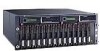
CAUTION: Use appropriate precautions when handling Fibre Channel cables: • Touching the end of a Fibre Channel cable will either damage the cable or cause performance problems, including intermittent difficulties accessing the storage. • Whenever a Fibre Channel cable is not connected, replace the protective covers on the ends of the cable. • Make certain that the Fibre Channel cables are installed and supported so that no excess weight is placed on the connectors. This prevents damage to the connector and cable. Excess cable should be loosely coiled and tied out of the way, being careful not to coil the cable in a tight loop with a bend radius of less than 3 inches (7.62 cm). 1. Review all warnings, cautions, and preparation procedures as detailed in Warnings and precautions. 2. Disconnect the cable from the Fibre Channel I/O module. 3. While grasping the module handle (1), slide the release latch to the right. (2). 4. Pull the module out of the chassis (3). 2 3 1 15569 Installing the component 1. Slide the replacement Fibre Channel I/O module into the MSA chassis bay until the module clicks into place. 2. Either move the SFP transceiver from the old Fibre Channel I/O module or install a new SFP transceiver in the new module. For instructions on removing and installing an SFP, see Replacing a 2-Gb small form factor pluggable (SFP) transceiver . 3. Reconnect the cables. Verifying proper operation After replacing the failed Fibre Channel I/O module verify that: • The Fibre Channel I/O module status LED is solid green. • Verify that the 1-Gb link status is solid green. • Verify that the 2-Gb link status is solid green. • No new error messages are displayed on the array controller LCD panel. 84 Customer replaceable components
-
 1
1 -
2
-
3
-
4
-
5
-
6
-
7
-
8
-
9
-
10
-
11
-
12
-
13
-
14
-
15
-
16
-
17
-
18
-
19
-
20
-
21
-
22
-
23
-
24
-
25
-
26
-
27
-
28
-
29
-
30
-
31
-
32
-
33
-
34
-
35
-
36
-
37
-
38
-
39
-
40
-
41
-
42
-
43
-
44
-
45
-
46
-
47
-
48
-
49
-
50
-
51
-
52
-
53
-
54
-
55
-
56
-
57
-
58
-
59
-
60
-
61
-
62
-
63
-
64
-
65
-
66
-
67
-
68
-
69
-
70
-
71
-
72
-
73
-
74
-
75
-
76
-
77
-
78
-
 79
79 -
 80
80 -
 81
81 -
 82
82 -
 83
83 -
 84
84 -
 85
85 -
 86
86 -
 87
87 -
 88
88 -
 89
89 -
90
-
91
-
92
-
93
-
94
-
95
-
96
-
97
-
98
-
99
-
100
-
101
-
102
-
103
-
104
-
105
-
106
-
107
-
108
-
109
-
110
-
111
-
112
-
113
-
114
-
115
-
116
-
117
-
118
-
119
-
120
-
121
-
122
 |
 |
