HP 610 Compaq 615 Notebook PC and Compaq 610 Notebook PC - Maintenance and Ser - Page 60
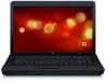
the module opposite the slot rises away from the computer.
 |
UPC - 884962591246
View all HP 610 manuals
Add to My Manuals
Save this manual to your list of manuals |
Page 60 highlights
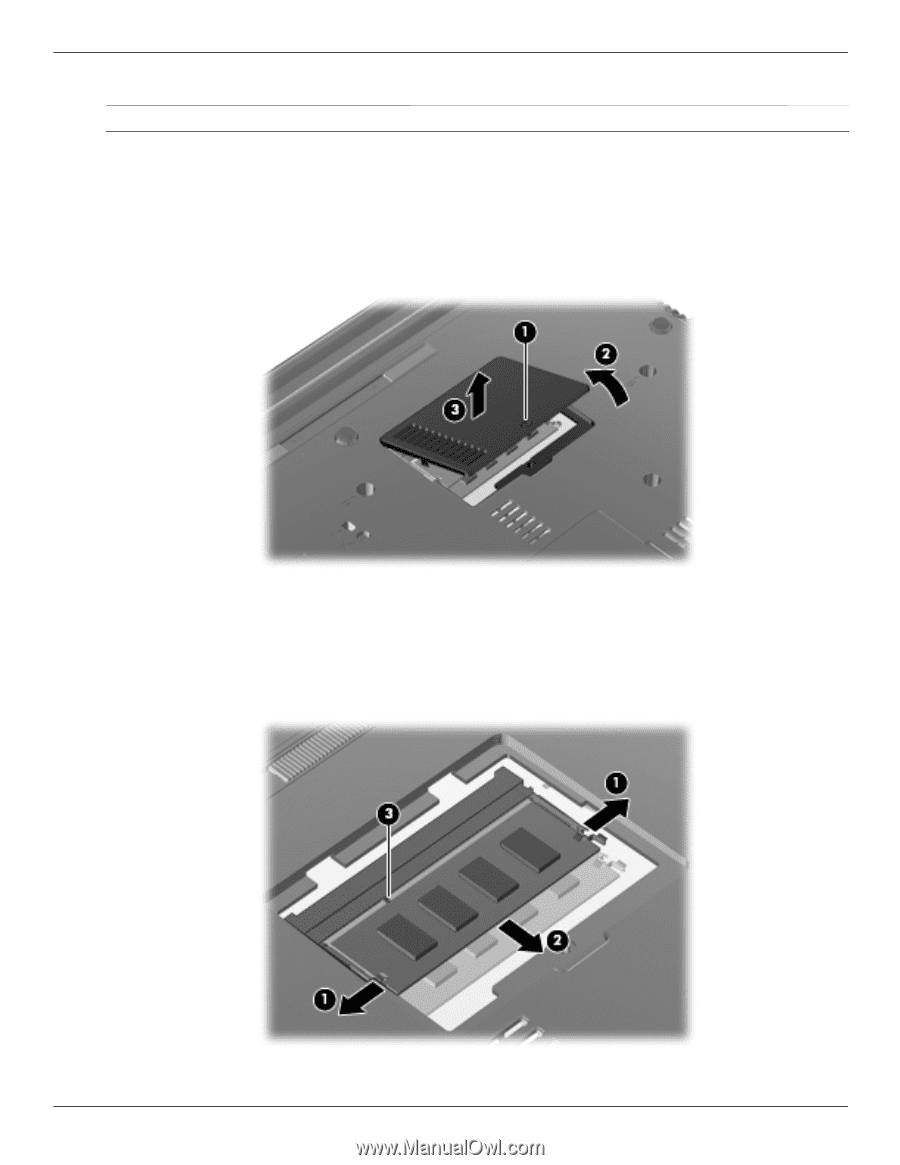
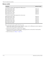
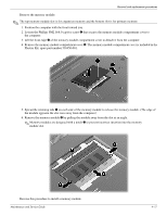
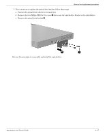
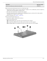
Removal and replacement procedures Remove the memory module: ✎ The top memory module slot is for expansion memory and the bottom slot is for primary memory. 1. Position the computer with the front toward you. 2. Loosen the Phillips PM2.0×6.0 captive screw 1 that secures the memory module compartment cover to the computer. 3. Lift the front edge 2 of the memory module compartment cover to detach it from the computer. 4. Remove the memory module compartment cover 3. The memory module compartment cover is included in the Plastics Kit, spare part number 538450-001. 5. Spread the retaining tabs 1 on each side of the memory module to release the memory module. (The edge of the module opposite the slot rises away from the computer.) 6. Remove the memory module 2 by pulling the module away from the slot at an angle. ✎ Memory modules are designed with a notch 3 to prevent incorrect insertion into the memory module slot. Reverse this procedure to install a memory module. Maintenance and Service Guide 4-17
-
 1
1 -
2
-
3
-
4
-
5
-
6
-
7
-
8
-
9
-
10
-
11
-
12
-
13
-
14
-
15
-
16
-
17
-
18
-
19
-
20
-
21
-
22
-
23
-
24
-
25
-
26
-
27
-
28
-
29
-
30
-
31
-
32
-
33
-
34
-
35
-
36
-
37
-
38
-
39
-
40
-
41
-
42
-
43
-
44
-
45
-
46
-
47
-
48
-
49
-
50
-
51
-
52
-
53
-
54
-
 55
55 -
 56
56 -
 57
57 -
 58
58 -
 59
59 -
 60
60 -
 61
61 -
 62
62 -
 63
63 -
 64
64 -
 65
65 -
66
-
67
-
68
-
69
-
70
-
71
-
72
-
73
-
74
-
75
-
76
-
77
-
78
-
79
-
80
-
81
-
82
-
83
-
84
-
85
-
86
-
87
-
88
-
89
-
90
-
91
-
92
-
93
-
94
-
95
-
96
-
97
-
98
-
99
-
100
-
101
-
102
-
103
-
104
-
105
-
106
-
107
-
108
-
109
-
110
-
111
-
112
-
113
-
114
-
115
-
116
-
117
-
118
-
119
-
120
-
121
-
122
-
123
-
124
-
125
-
126
-
127
-
128
-
129
-
130
-
131
-
132
-
133
-
134
-
135
-
136
-
137
-
138
-
139
-
140
-
141
-
142
-
143
-
144
-
145
-
146
-
147
-
148
-
149
-
150
-
151
-
152
-
153
-
154
 |
 |