HP 610 Compaq 615 Notebook PC and Compaq 610 Notebook PC - Maintenance and Ser - Page 70
that secure the display assembly to the computer., Lift the display assembly
 |
UPC - 884962591246
View all HP 610 manuals
Add to My Manuals
Save this manual to your list of manuals |
Page 70 highlights
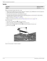
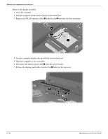
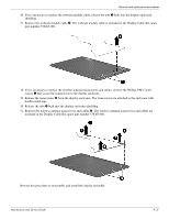
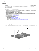
Removal and replacement procedures 8. Disconnect the webcam module cable 1 from the system board. 9. Remove the wireless antenna cables 2 and the microphone cable from the clips 3 and routing channel built into the top cover. Ä CAUTION: Support the display assembly when removing the following screws. Failure to support the display assembly can result in damage to the display assembly and other computer components. 10. Remove the four Phillips PM2.5×6.0 screws 1 that secure the display assembly to the computer. 11. Lift the display assembly 2 straight up and remove it. Maintenance and Service Guide 4-27
-
 1
1 -
2
-
3
-
4
-
5
-
6
-
7
-
8
-
9
-
10
-
11
-
12
-
13
-
14
-
15
-
16
-
17
-
18
-
19
-
20
-
21
-
22
-
23
-
24
-
25
-
26
-
27
-
28
-
29
-
30
-
31
-
32
-
33
-
34
-
35
-
36
-
37
-
38
-
39
-
40
-
41
-
42
-
43
-
44
-
45
-
46
-
47
-
48
-
49
-
50
-
51
-
52
-
53
-
54
-
55
-
56
-
57
-
58
-
59
-
60
-
61
-
62
-
63
-
64
-
 65
65 -
 66
66 -
 67
67 -
 68
68 -
 69
69 -
 70
70 -
 71
71 -
 72
72 -
 73
73 -
 74
74 -
 75
75 -
76
-
77
-
78
-
79
-
80
-
81
-
82
-
83
-
84
-
85
-
86
-
87
-
88
-
89
-
90
-
91
-
92
-
93
-
94
-
95
-
96
-
97
-
98
-
99
-
100
-
101
-
102
-
103
-
104
-
105
-
106
-
107
-
108
-
109
-
110
-
111
-
112
-
113
-
114
-
115
-
116
-
117
-
118
-
119
-
120
-
121
-
122
-
123
-
124
-
125
-
126
-
127
-
128
-
129
-
130
-
131
-
132
-
133
-
134
-
135
-
136
-
137
-
138
-
139
-
140
-
141
-
142
-
143
-
144
-
145
-
146
-
147
-
148
-
149
-
150
-
151
-
152
-
153
-
154
 |
 |
Removal and replacement procedures
Maintenance and Service Guide
4–27
8. Disconnect the webcam module cable
1
from the system board.
9. Remove the wireless antenna cables
2
and the microphone cable from the clips
3
and routing channel built
into the top cover.
Ä
CAUTION:
Support the display assembly when removing the following screws. Failure to support the display
assembly can result in damage to the display assembly and other computer components.
10. Remove the four Phillips PM2.5×6.0 screws
1
that secure the display assembly to the computer.
11. Lift the display assembly
2
straight up and remove it.