HP 610 Compaq 615 Notebook PC and Compaq 610 Notebook PC - Maintenance and Ser - Page 79
Remove the Phillips PM2.5×4.0 screw, until the external monitor connector
 |
UPC - 884962591246
View all HP 610 manuals
Add to My Manuals
Save this manual to your list of manuals |
Page 79 highlights
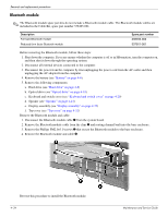
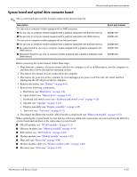
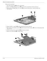
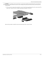
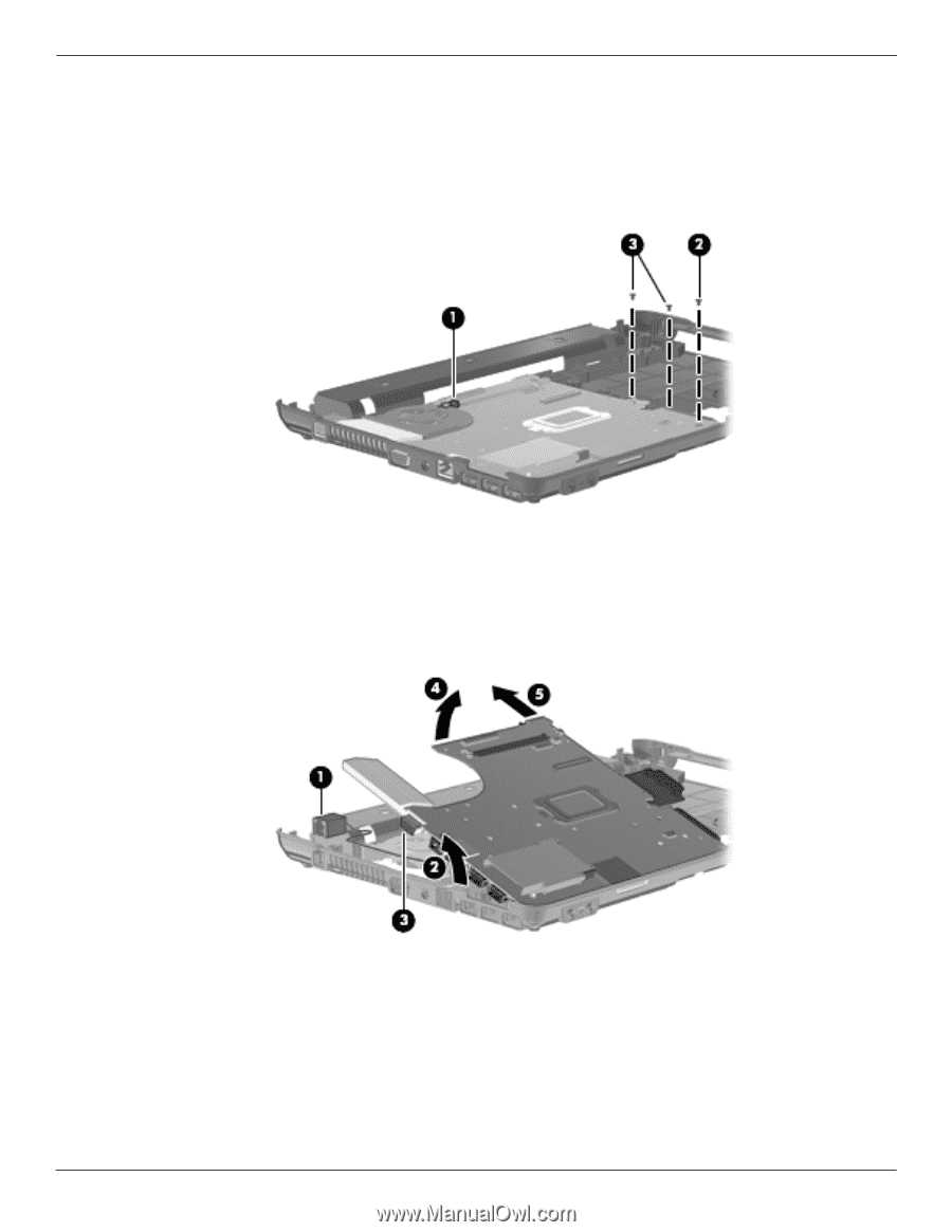
Removal and replacement procedures Remove the system board: 1. Disconnect the fan cable 1 from the system board. 2. Remove the Phillips PM2.5×4.0 screw 2 that secures the system board to the base enclosure. 3. Remove the two Phillips PM2.5×4.0 screws 3 that secure the optical drive connector board to the base enclosure. 4. Release the RJ-11 connector 1 from the clip built into the base enclosure. 5. Flex the left side of the base enclosure 2 until the external monitor connector 3 is clear of the opening of the base enclosure. 6. Lift the rear edge of the system board 4 until it rests at an angle. 7. Remove the system board 5 by sliding it back. 4-36 Maintenance and Service Guide
-
 1
1 -
2
-
3
-
4
-
5
-
6
-
7
-
8
-
9
-
10
-
11
-
12
-
13
-
14
-
15
-
16
-
17
-
18
-
19
-
20
-
21
-
22
-
23
-
24
-
25
-
26
-
27
-
28
-
29
-
30
-
31
-
32
-
33
-
34
-
35
-
36
-
37
-
38
-
39
-
40
-
41
-
42
-
43
-
44
-
45
-
46
-
47
-
48
-
49
-
50
-
51
-
52
-
53
-
54
-
55
-
56
-
57
-
58
-
59
-
60
-
61
-
62
-
63
-
64
-
65
-
66
-
67
-
68
-
69
-
70
-
71
-
72
-
73
-
 74
74 -
 75
75 -
 76
76 -
 77
77 -
 78
78 -
 79
79 -
 80
80 -
 81
81 -
 82
82 -
 83
83 -
 84
84 -
85
-
86
-
87
-
88
-
89
-
90
-
91
-
92
-
93
-
94
-
95
-
96
-
97
-
98
-
99
-
100
-
101
-
102
-
103
-
104
-
105
-
106
-
107
-
108
-
109
-
110
-
111
-
112
-
113
-
114
-
115
-
116
-
117
-
118
-
119
-
120
-
121
-
122
-
123
-
124
-
125
-
126
-
127
-
128
-
129
-
130
-
131
-
132
-
133
-
134
-
135
-
136
-
137
-
138
-
139
-
140
-
141
-
142
-
143
-
144
-
145
-
146
-
147
-
148
-
149
-
150
-
151
-
152
-
153
-
154
 |
 |
4–36
Maintenance and Service Guide
Removal and replacement procedures
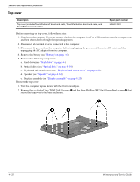
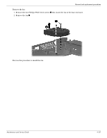
Remove the system board:
1. Disconnect the fan cable
1
from the system board.
2. Remove the Phillips PM2.5×4.0 screw
2
that secures the system board to the base enclosure.
3. Remove the two Phillips PM2.5×4.0 screws
3
that secure the optical drive connector board to the
base enclosure.
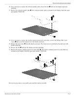
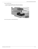
4. Release the RJ-11 connector
1
from the clip built into the base enclosure.
5. Flex the left side of the base enclosure
2
until the external monitor connector
3
is clear of the opening of the
base enclosure.
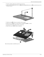
6. Lift the rear edge of the system board
4
until it rests at an angle.
7. Remove the system board
5
by sliding it back.