HP 610 Compaq 615 Notebook PC and Compaq 610 Notebook PC - Maintenance and Ser - Page 78
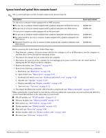
System board and optical drive connector board
 |
UPC - 884962591246
View all HP 610 manuals
Add to My Manuals
Save this manual to your list of manuals |
Page 78 highlights
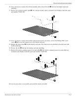
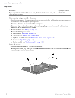
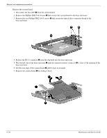
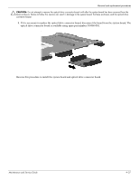
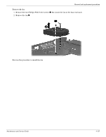
Removal and replacement procedures System board and optical drive connector board ✎ The system board spare part kit includes replacement thermal material. Description For use only on computer models equipped with an AMD processor: ■ For use only on computer models equipped with a graphics subsystem with discrete memory ■ For use only on computer models equipped with a graphics subsystem with UMA memory For use only on computer models equipped with an Intel processor: ■ For use only on computer models equipped with a graphics subsystem with discrete memory ■ GL system board for use only on computer models equipped with a graphics subsystem with UMA memory ■ GM system board for use only on computer models equipped with a graphics subsystem with UMA memory Spare part number 538392-001 538391-001 538408-001 538407-001 538409-001 Before removing the system board, follow these steps: 1. Shut down the computer. If you are unsure whether the computer is off or in Hibernation, turn the computer on, and then shut it down through the operating system. 2. Disconnect all external devices connected to the computer. 3. Disconnect the power from the computer by first unplugging the power cord from the AC outlet and then unplugging the AC adapter from the computer. 4. Remove the battery (see "Battery" on page 4-6). 5. Remove the following components: a. Hard drive (see "Hard drive" on page 4-8) b. Optical drive (see "Optical drive" on page 4-18) c. Keyboard and switch cover (see "Keyboard and switch cover" on page 4-20) d. Speaker (see "Speaker" on page 4-24) e. Display assembly (see "Display assembly" on page 4-25) f. Top cover (see "Top cover" on page 4-32) 6. Disconnect the Bluetooth module cable from the system board (see "Bluetooth module" on page 4-34). When replacing the system board, be sure that the following additional components are removed from the defective system board and installed on the replacement system board: ■ WLAN module (see "WLAN module" on page 4-12) ■ Memory modules (see "Memory module" on page 4-16) ■ RTC battery (see "RTC battery" on page 4-40) ■ Modem module (see "Modem module" on page 4-42) ■ Heat sink (see "Heat sink" on page 4-44) ■ Modem module cable (see "Modem module cable" on page 4-48) ■ Processor (see "Processor" on page 4-49) Maintenance and Service Guide 4-35
-
 1
1 -
2
-
3
-
4
-
5
-
6
-
7
-
8
-
9
-
10
-
11
-
12
-
13
-
14
-
15
-
16
-
17
-
18
-
19
-
20
-
21
-
22
-
23
-
24
-
25
-
26
-
27
-
28
-
29
-
30
-
31
-
32
-
33
-
34
-
35
-
36
-
37
-
38
-
39
-
40
-
41
-
42
-
43
-
44
-
45
-
46
-
47
-
48
-
49
-
50
-
51
-
52
-
53
-
54
-
55
-
56
-
57
-
58
-
59
-
60
-
61
-
62
-
63
-
64
-
65
-
66
-
67
-
68
-
69
-
70
-
71
-
72
-
 73
73 -
 74
74 -
 75
75 -
 76
76 -
 77
77 -
 78
78 -
 79
79 -
 80
80 -
 81
81 -
 82
82 -
 83
83 -
84
-
85
-
86
-
87
-
88
-
89
-
90
-
91
-
92
-
93
-
94
-
95
-
96
-
97
-
98
-
99
-
100
-
101
-
102
-
103
-
104
-
105
-
106
-
107
-
108
-
109
-
110
-
111
-
112
-
113
-
114
-
115
-
116
-
117
-
118
-
119
-
120
-
121
-
122
-
123
-
124
-
125
-
126
-
127
-
128
-
129
-
130
-
131
-
132
-
133
-
134
-
135
-
136
-
137
-
138
-
139
-
140
-
141
-
142
-
143
-
144
-
145
-
146
-
147
-
148
-
149
-
150
-
151
-
152
-
153
-
154
 |
 |