HP 610 Compaq 615 Notebook PC and Compaq 610 Notebook PC - Maintenance and Ser - Page 89
Loosen the four Phillips PM2.5×9.0 captive screws, discrete memory.
 |
UPC - 884962591246
View all HP 610 manuals
Add to My Manuals
Save this manual to your list of manuals |
Page 89 highlights
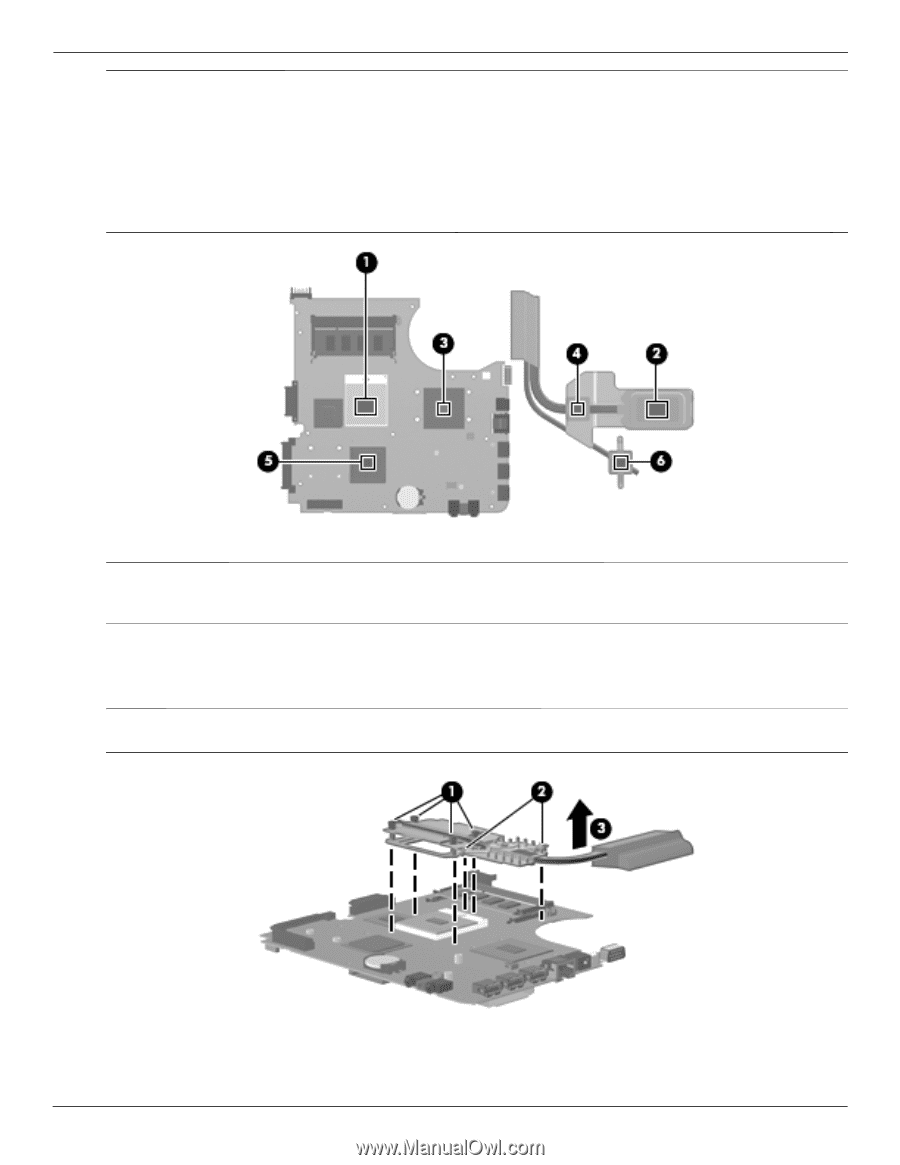
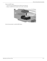
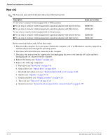
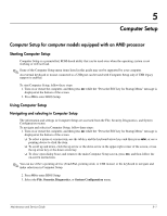
Removal and replacement procedures ✎ The thermal material must be thoroughly cleaned from the surfaces of the heat sink and the system board each time the heat sink is removed: ■ Thermal paste is used on the processor 1 and the heat sink section 2 that services it. ■ Thermal pads are used on the Northbridge chip 3 and the heat sink section 4 that services it. ■ Thermal pads are used on the graphics subsystem memory module 5 and the heat sink section 6 that services it. Replacement thermal material is included with all system board, heat sink, and processor spare part kits. ✎ Steps 4 and 5 apply to computer models equipped with graphics subsystems with UMA memory. See steps 2 and 3 for instructions on removing the heat sink on computer models equipped with graphics subsystems with discrete memory. 4. Loosen the four Phillips PM2.5×9.0 captive screws 1 and the two Phillips PM2.0×5.0 captive screws 2 that secure the heat sink to the system board. 5. Remove the heat sink 3. ✎ Due to the adhesive quality of the thermal material located between the heat sink and system board components, it may be necessary to move the heat sink from side to side to detach the heat sink. 4-46 Maintenance and Service Guide
-
 1
1 -
2
-
3
-
4
-
5
-
6
-
7
-
8
-
9
-
10
-
11
-
12
-
13
-
14
-
15
-
16
-
17
-
18
-
19
-
20
-
21
-
22
-
23
-
24
-
25
-
26
-
27
-
28
-
29
-
30
-
31
-
32
-
33
-
34
-
35
-
36
-
37
-
38
-
39
-
40
-
41
-
42
-
43
-
44
-
45
-
46
-
47
-
48
-
49
-
50
-
51
-
52
-
53
-
54
-
55
-
56
-
57
-
58
-
59
-
60
-
61
-
62
-
63
-
64
-
65
-
66
-
67
-
68
-
69
-
70
-
71
-
72
-
73
-
74
-
75
-
76
-
77
-
78
-
79
-
80
-
81
-
82
-
83
-
 84
84 -
 85
85 -
 86
86 -
 87
87 -
 88
88 -
 89
89 -
 90
90 -
 91
91 -
 92
92 -
 93
93 -
 94
94 -
95
-
96
-
97
-
98
-
99
-
100
-
101
-
102
-
103
-
104
-
105
-
106
-
107
-
108
-
109
-
110
-
111
-
112
-
113
-
114
-
115
-
116
-
117
-
118
-
119
-
120
-
121
-
122
-
123
-
124
-
125
-
126
-
127
-
128
-
129
-
130
-
131
-
132
-
133
-
134
-
135
-
136
-
137
-
138
-
139
-
140
-
141
-
142
-
143
-
144
-
145
-
146
-
147
-
148
-
149
-
150
-
151
-
152
-
153
-
154
 |
 |