HP 610 Compaq 615 Notebook PC and Compaq 610 Notebook PC - Maintenance and Ser - Page 74
Release the tabs, double-sided tape.
 |
UPC - 884962591246
View all HP 610 manuals
Add to My Manuals
Save this manual to your list of manuals |
Page 74 highlights
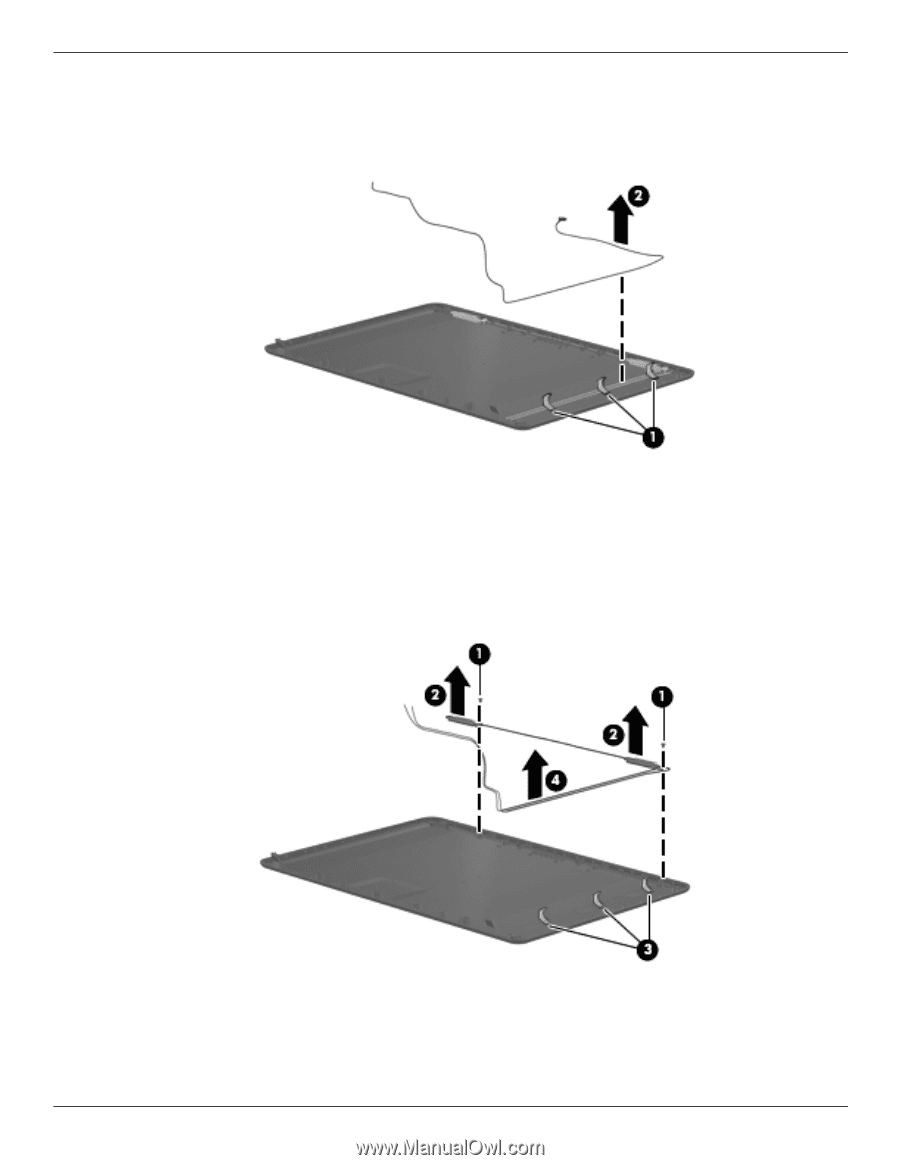
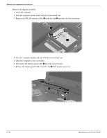
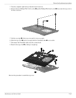
Removal and replacement procedures 26. If it is necessary to replace the webcam module cable, release the tabs 1 built into the display enclosure shielding. 27. Remove the webcam module cable 2. The webcam module cable is included in the Display Cable Kit, spare part number 538463-001. 28. If it is necessary to replace the wireless antenna transceivers and cables, remove the Phillips PM2.5×4.0 screws 1 that secure the transceivers to the display enclosure. 29. Release the transceivers 2 from the display enclosure. The transceivers are attached to the enclosure with double-sided tape. 30. Release the tabs 3 built into the display enclosure shielding. 31. Remove the wireless antenna transceivers and cables 4. The wireless antenna transceivers and cables are included in the Display Cable Kit, spare part number 538463-001. Reverse this procedure to reassemble and install the display assembly. Maintenance and Service Guide 4-31
-
 1
1 -
2
-
3
-
4
-
5
-
6
-
7
-
8
-
9
-
10
-
11
-
12
-
13
-
14
-
15
-
16
-
17
-
18
-
19
-
20
-
21
-
22
-
23
-
24
-
25
-
26
-
27
-
28
-
29
-
30
-
31
-
32
-
33
-
34
-
35
-
36
-
37
-
38
-
39
-
40
-
41
-
42
-
43
-
44
-
45
-
46
-
47
-
48
-
49
-
50
-
51
-
52
-
53
-
54
-
55
-
56
-
57
-
58
-
59
-
60
-
61
-
62
-
63
-
64
-
65
-
66
-
67
-
68
-
 69
69 -
 70
70 -
 71
71 -
 72
72 -
 73
73 -
 74
74 -
 75
75 -
 76
76 -
 77
77 -
 78
78 -
 79
79 -
80
-
81
-
82
-
83
-
84
-
85
-
86
-
87
-
88
-
89
-
90
-
91
-
92
-
93
-
94
-
95
-
96
-
97
-
98
-
99
-
100
-
101
-
102
-
103
-
104
-
105
-
106
-
107
-
108
-
109
-
110
-
111
-
112
-
113
-
114
-
115
-
116
-
117
-
118
-
119
-
120
-
121
-
122
-
123
-
124
-
125
-
126
-
127
-
128
-
129
-
130
-
131
-
132
-
133
-
134
-
135
-
136
-
137
-
138
-
139
-
140
-
141
-
142
-
143
-
144
-
145
-
146
-
147
-
148
-
149
-
150
-
151
-
152
-
153
-
154
 |
 |