HP 610 Compaq 615 Notebook PC and Compaq 610 Notebook PC - Maintenance and Ser - Page 71
of the display bezel, and the bottom edge
 |
UPC - 884962591246
View all HP 610 manuals
Add to My Manuals
Save this manual to your list of manuals |
Page 71 highlights
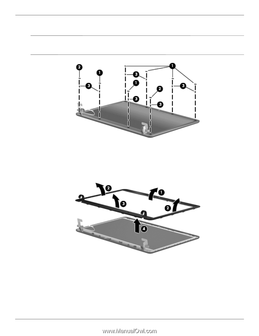
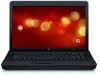
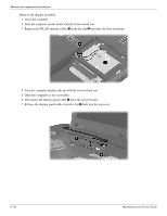
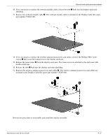
Removal and replacement procedures 12. If it is necessary to replace the display bezel or any of the display assembly internal components, remove the eight rubber screw covers 1 and 2 and the eight Phillips PM2.5×6.0 screws 3. ✎ The rubber screw covers 1 on the display bezel top edge and bottom inside edge are larger than the rubber screw covers 2 on the display bezel bottom outside corners. The rubber screw covers are included in the Rubber Kit, spare part number 538448-001. 13. Flex the inside edges of the top edge 1, the left and right sides 2, and the bottom edge 3 of the display bezel until the bezel disengages from the display enclosure. 14. Remove the display bezel 4. The display bezel is available using the following spare part numbers: ❏ 538428-001-for use only on computer models equipped with a webcam ❏ 538427-001-for use only on computer models not equipped with a webcam 4-28 Maintenance and Service Guide
-
 1
1 -
2
-
3
-
4
-
5
-
6
-
7
-
8
-
9
-
10
-
11
-
12
-
13
-
14
-
15
-
16
-
17
-
18
-
19
-
20
-
21
-
22
-
23
-
24
-
25
-
26
-
27
-
28
-
29
-
30
-
31
-
32
-
33
-
34
-
35
-
36
-
37
-
38
-
39
-
40
-
41
-
42
-
43
-
44
-
45
-
46
-
47
-
48
-
49
-
50
-
51
-
52
-
53
-
54
-
55
-
56
-
57
-
58
-
59
-
60
-
61
-
62
-
63
-
64
-
65
-
 66
66 -
 67
67 -
 68
68 -
 69
69 -
 70
70 -
 71
71 -
 72
72 -
 73
73 -
 74
74 -
 75
75 -
 76
76 -
77
-
78
-
79
-
80
-
81
-
82
-
83
-
84
-
85
-
86
-
87
-
88
-
89
-
90
-
91
-
92
-
93
-
94
-
95
-
96
-
97
-
98
-
99
-
100
-
101
-
102
-
103
-
104
-
105
-
106
-
107
-
108
-
109
-
110
-
111
-
112
-
113
-
114
-
115
-
116
-
117
-
118
-
119
-
120
-
121
-
122
-
123
-
124
-
125
-
126
-
127
-
128
-
129
-
130
-
131
-
132
-
133
-
134
-
135
-
136
-
137
-
138
-
139
-
140
-
141
-
142
-
143
-
144
-
145
-
146
-
147
-
148
-
149
-
150
-
151
-
152
-
153
-
154
 |
 |