HP Dc7700 HP Compaq dc7700 Business Desktop PC Service Reference Guide, 1st Ed - Page 113
Reposition the bezel blanks within the subpanel in the proper orientation for the desktop
 |
UPC - 882780715318
View all HP Dc7700 manuals
Add to My Manuals
Save this manual to your list of manuals |
Page 113 highlights
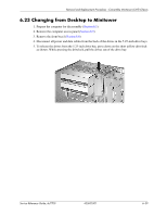
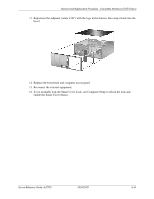
Removal and Replacement Procedures - Convertible Minitower (CMT) Chassis 6. Before reinstalling each drive into the chassis, turn the drive so that it is perpendicular to the internal 3.5-inch drive. The drive should be parallel to the green latch drive bracket. 7. Slide the drive into the uppermost available bay until it snaps into place. When the drive is properly inserted, the drivelock will secure it. Repeat this step for each drive. Ä CAUTION: The bottom 5.25-inch drive bay has a shorter depth than the upper two bays. The bottom bay supports a drive that is no more than 17 cm (6.7 inches) in depth, including the cables that attach to the back of the drive. Do not try to force a larger drive, such as an optical drive, into the bottom bay. This could cause damage to the drive and the system board. The use of unnecessary force when installing any drive into the drive bay may result in damage to the drive. 8. Reconnect all power and data cables to the drives in the 5.25-inch drive bays. 9. Remove the bezel subpanel (Section 6.7). Ä CAUTION: Hold the subpanel straight when you pull it away from the front bezel. Pulling the subpanel away at an angle could damage the pins that align it within the front bezel. 10. Reposition the bezel blanks within the subpanel in the proper orientation for the desktop configuration. Service Reference Guide, dc7700 433612-001 6-43
-
 1
1 -
2
-
3
-
4
-
5
-
6
-
7
-
8
-
9
-
10
-
11
-
12
-
13
-
14
-
15
-
16
-
17
-
18
-
19
-
20
-
21
-
22
-
23
-
24
-
25
-
26
-
27
-
28
-
29
-
30
-
31
-
32
-
33
-
34
-
35
-
36
-
37
-
38
-
39
-
40
-
41
-
42
-
43
-
44
-
45
-
46
-
47
-
48
-
49
-
50
-
51
-
52
-
53
-
54
-
55
-
56
-
57
-
58
-
59
-
60
-
61
-
62
-
63
-
64
-
65
-
66
-
67
-
68
-
69
-
70
-
71
-
72
-
73
-
74
-
75
-
76
-
77
-
78
-
79
-
80
-
81
-
82
-
83
-
84
-
85
-
86
-
87
-
88
-
89
-
90
-
91
-
92
-
93
-
94
-
95
-
96
-
97
-
98
-
99
-
100
-
101
-
102
-
103
-
104
-
105
-
106
-
107
-
 108
108 -
 109
109 -
 110
110 -
 111
111 -
 112
112 -
 113
113 -
 114
114 -
 115
115 -
 116
116 -
 117
117 -
 118
118 -
119
-
120
-
121
-
122
-
123
-
124
-
125
-
126
-
127
-
128
-
129
-
130
-
131
-
132
-
133
-
134
-
135
-
136
-
137
-
138
-
139
-
140
-
141
-
142
-
143
-
144
-
145
-
146
-
147
-
148
-
149
-
150
-
151
-
152
-
153
-
154
-
155
-
156
-
157
-
158
-
159
-
160
-
161
-
162
-
163
-
164
-
165
-
166
-
167
-
168
-
169
-
170
-
171
-
172
-
173
-
174
-
175
-
176
-
177
-
178
-
179
-
180
-
181
-
182
-
183
-
184
-
185
-
186
-
187
-
188
-
189
-
190
-
191
-
192
-
193
-
194
-
195
-
196
-
197
-
198
-
199
-
200
-
201
-
202
-
203
-
204
-
205
-
206
-
207
-
208
-
209
-
210
-
211
-
212
-
213
-
214
-
215
-
216
-
217
-
218
-
219
-
220
-
221
-
222
-
223
-
224
-
225
-
226
-
227
-
228
-
229
-
230
-
231
-
232
-
233
-
234
-
235
-
236
-
237
-
238
-
239
-
240
-
241
-
242
-
243
-
244
-
245
-
246
-
247
-
248
-
249
-
250
-
251
-
252
-
253
-
254
-
255
-
256
-
257
-
258
-
259
-
260
-
261
-
262
-
263
-
264
-
265
-
266
-
267
-
268
 |
 |
