HP Dc7700 HP Compaq dc7700 Business Desktop PC Service Reference Guide, 1st Ed - Page 143
exactly the same as the factory-installed cable.
 |
UPC - 882780715318
View all HP Dc7700 manuals
Add to My Manuals
Save this manual to your list of manuals |
Page 143 highlights
Removal and Replacement Procedures- Small Form Factor (SFF) Chassis 7. Disconnect the power and data cables from the back of the hard drive. 8. Pull the tab that locks the drive in place away from the drive 1, slide the hard drive toward the front of the computer, then lift it up and out of the bay 2. To install a hard drive, reverse the above procedure. ✎ The replacement hard drive kit includes several data cables. Make sure to use the cable that is exactly the same as the factory-installed cable. ✎ If the system has only one SATA hard drive, the data cable must be connected to the dark blue connector labeled SATA0 first to avoid any hard drive performance problems. Service Reference Guide, dc7700 433612-001 7-29
-
 1
1 -
2
-
3
-
4
-
5
-
6
-
7
-
8
-
9
-
10
-
11
-
12
-
13
-
14
-
15
-
16
-
17
-
18
-
19
-
20
-
21
-
22
-
23
-
24
-
25
-
26
-
27
-
28
-
29
-
30
-
31
-
32
-
33
-
34
-
35
-
36
-
37
-
38
-
39
-
40
-
41
-
42
-
43
-
44
-
45
-
46
-
47
-
48
-
49
-
50
-
51
-
52
-
53
-
54
-
55
-
56
-
57
-
58
-
59
-
60
-
61
-
62
-
63
-
64
-
65
-
66
-
67
-
68
-
69
-
70
-
71
-
72
-
73
-
74
-
75
-
76
-
77
-
78
-
79
-
80
-
81
-
82
-
83
-
84
-
85
-
86
-
87
-
88
-
89
-
90
-
91
-
92
-
93
-
94
-
95
-
96
-
97
-
98
-
99
-
100
-
101
-
102
-
103
-
104
-
105
-
106
-
107
-
108
-
109
-
110
-
111
-
112
-
113
-
114
-
115
-
116
-
117
-
118
-
119
-
120
-
121
-
122
-
123
-
124
-
125
-
126
-
127
-
128
-
129
-
130
-
131
-
132
-
133
-
134
-
135
-
136
-
137
-
 138
138 -
 139
139 -
 140
140 -
 141
141 -
 142
142 -
 143
143 -
 144
144 -
 145
145 -
 146
146 -
 147
147 -
 148
148 -
149
-
150
-
151
-
152
-
153
-
154
-
155
-
156
-
157
-
158
-
159
-
160
-
161
-
162
-
163
-
164
-
165
-
166
-
167
-
168
-
169
-
170
-
171
-
172
-
173
-
174
-
175
-
176
-
177
-
178
-
179
-
180
-
181
-
182
-
183
-
184
-
185
-
186
-
187
-
188
-
189
-
190
-
191
-
192
-
193
-
194
-
195
-
196
-
197
-
198
-
199
-
200
-
201
-
202
-
203
-
204
-
205
-
206
-
207
-
208
-
209
-
210
-
211
-
212
-
213
-
214
-
215
-
216
-
217
-
218
-
219
-
220
-
221
-
222
-
223
-
224
-
225
-
226
-
227
-
228
-
229
-
230
-
231
-
232
-
233
-
234
-
235
-
236
-
237
-
238
-
239
-
240
-
241
-
242
-
243
-
244
-
245
-
246
-
247
-
248
-
249
-
250
-
251
-
252
-
253
-
254
-
255
-
256
-
257
-
258
-
259
-
260
-
261
-
262
-
263
-
264
-
265
-
266
-
267
-
268
 |
 |

Service Reference Guide, dc7700
433612-001
7–29
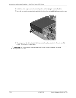
Removal and Replacement Procedures— Small Form Factor (SFF) Chassis
7. Disconnect the power and data cables from the back of the hard drive.
8. Pull the tab that locks the drive in place away from the drive
1
, slide the hard drive toward
the front of the computer, then lift it up and out of the bay
2
.
To install a hard drive, reverse the above procedure.
✎
The replacement hard drive kit includes several data cables. Make sure to use the cable that is
exactly the same as the factory-installed cable.
✎
If the system has only one SATA hard drive, the data cable must be connected to the
dark
blue
connector labeled SATA0 first to avoid any hard drive performance problems.