HP Dc7700 HP Compaq dc7700 Business Desktop PC Service Reference Guide, 1st Ed - Page 97
Power Switch Assembly
 |
UPC - 882780715318
View all HP Dc7700 manuals
Add to My Manuals
Save this manual to your list of manuals |
Page 97 highlights
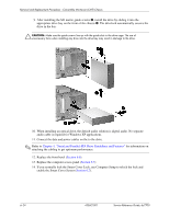
Removal and Replacement Procedures - Convertible Minitower (CMT) Chassis 6.15 Power Switch Assembly 1. Prepare the computer for disassembly (Section 6.1). 2. Remove the computer access panel (Section 6.5). 3. Remove the front bezel (Section 6.6). 4. Disconnect the power switch/LED cable from the system board. 5. Squeeze the switch holder retaining clips together at the front of the chassis 1 and pull the switch assembly out of the chassis 2. To install the power switch assembly, reverse the removal procedure. ✎ When installing the power switch cable it may be necessary to disconnect a data cabe from one of the drives to make it easier to grab the free end of the cable. Service Reference Guide, dc7700 433612-001 6-27
-
 1
1 -
2
-
3
-
4
-
5
-
6
-
7
-
8
-
9
-
10
-
11
-
12
-
13
-
14
-
15
-
16
-
17
-
18
-
19
-
20
-
21
-
22
-
23
-
24
-
25
-
26
-
27
-
28
-
29
-
30
-
31
-
32
-
33
-
34
-
35
-
36
-
37
-
38
-
39
-
40
-
41
-
42
-
43
-
44
-
45
-
46
-
47
-
48
-
49
-
50
-
51
-
52
-
53
-
54
-
55
-
56
-
57
-
58
-
59
-
60
-
61
-
62
-
63
-
64
-
65
-
66
-
67
-
68
-
69
-
70
-
71
-
72
-
73
-
74
-
75
-
76
-
77
-
78
-
79
-
80
-
81
-
82
-
83
-
84
-
85
-
86
-
87
-
88
-
89
-
90
-
91
-
 92
92 -
 93
93 -
 94
94 -
 95
95 -
 96
96 -
 97
97 -
 98
98 -
 99
99 -
 100
100 -
 101
101 -
 102
102 -
103
-
104
-
105
-
106
-
107
-
108
-
109
-
110
-
111
-
112
-
113
-
114
-
115
-
116
-
117
-
118
-
119
-
120
-
121
-
122
-
123
-
124
-
125
-
126
-
127
-
128
-
129
-
130
-
131
-
132
-
133
-
134
-
135
-
136
-
137
-
138
-
139
-
140
-
141
-
142
-
143
-
144
-
145
-
146
-
147
-
148
-
149
-
150
-
151
-
152
-
153
-
154
-
155
-
156
-
157
-
158
-
159
-
160
-
161
-
162
-
163
-
164
-
165
-
166
-
167
-
168
-
169
-
170
-
171
-
172
-
173
-
174
-
175
-
176
-
177
-
178
-
179
-
180
-
181
-
182
-
183
-
184
-
185
-
186
-
187
-
188
-
189
-
190
-
191
-
192
-
193
-
194
-
195
-
196
-
197
-
198
-
199
-
200
-
201
-
202
-
203
-
204
-
205
-
206
-
207
-
208
-
209
-
210
-
211
-
212
-
213
-
214
-
215
-
216
-
217
-
218
-
219
-
220
-
221
-
222
-
223
-
224
-
225
-
226
-
227
-
228
-
229
-
230
-
231
-
232
-
233
-
234
-
235
-
236
-
237
-
238
-
239
-
240
-
241
-
242
-
243
-
244
-
245
-
246
-
247
-
248
-
249
-
250
-
251
-
252
-
253
-
254
-
255
-
256
-
257
-
258
-
259
-
260
-
261
-
262
-
263
-
264
-
265
-
266
-
267
-
268
 |
 |

Service Reference Guide, dc7700
433612-001
6–27
Removal and Replacement Procedures - Convertible Minitower (CMT) Chassis
6.15 Power Switch Assembly
1. Prepare the computer for disassembly (
Section 6.1
).
2. Remove the computer access panel (
Section 6.5
).
3. Remove the front bezel (
Section 6.6
).
4. Disconnect the power switch/LED cable from the system board.
5. Squeeze the switch holder retaining clips together at the front of the chassis
1
and pull the
switch assembly out of the chassis
2
.
To install the power switch assembly, reverse the removal procedure.
✎
When installing the power switch cable it may be necessary to disconnect a data cabe from one
of the drives to make it easier to grab the free end of the cable.