HP Dc7700 HP Compaq dc7700 Business Desktop PC Service Reference Guide, 1st Ed - Page 171
Chassis Fan
 |
UPC - 882780715318
View all HP Dc7700 manuals
Add to My Manuals
Save this manual to your list of manuals |
Page 171 highlights
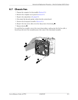
Removal and Replacement Procedures - Ultra-Slim Desktop (USDT) Chassis 8.7 Chassis Fan 1. Prepare the computer for disassembly (Section 8.1). 2. Remove the computer access panel (Section 8.3). 3. Remove the optical drive (Section 8.4). 4. Disconnect the fan and speaker cables from the system board. 5. Remove the front panel assembly (Section 8.5). 6. Remove the four screws that secure the chassis fan to the housing 1. 7. Remove the fan 2. To install the fan assembly, reverse the removal procedures, making sure that the fan cable is located near the top of the assembly nearest the center of the front panel assembly. Service Reference Guide, dc7700 433612-001 8-9
-
 1
1 -
2
-
3
-
4
-
5
-
6
-
7
-
8
-
9
-
10
-
11
-
12
-
13
-
14
-
15
-
16
-
17
-
18
-
19
-
20
-
21
-
22
-
23
-
24
-
25
-
26
-
27
-
28
-
29
-
30
-
31
-
32
-
33
-
34
-
35
-
36
-
37
-
38
-
39
-
40
-
41
-
42
-
43
-
44
-
45
-
46
-
47
-
48
-
49
-
50
-
51
-
52
-
53
-
54
-
55
-
56
-
57
-
58
-
59
-
60
-
61
-
62
-
63
-
64
-
65
-
66
-
67
-
68
-
69
-
70
-
71
-
72
-
73
-
74
-
75
-
76
-
77
-
78
-
79
-
80
-
81
-
82
-
83
-
84
-
85
-
86
-
87
-
88
-
89
-
90
-
91
-
92
-
93
-
94
-
95
-
96
-
97
-
98
-
99
-
100
-
101
-
102
-
103
-
104
-
105
-
106
-
107
-
108
-
109
-
110
-
111
-
112
-
113
-
114
-
115
-
116
-
117
-
118
-
119
-
120
-
121
-
122
-
123
-
124
-
125
-
126
-
127
-
128
-
129
-
130
-
131
-
132
-
133
-
134
-
135
-
136
-
137
-
138
-
139
-
140
-
141
-
142
-
143
-
144
-
145
-
146
-
147
-
148
-
149
-
150
-
151
-
152
-
153
-
154
-
155
-
156
-
157
-
158
-
159
-
160
-
161
-
162
-
163
-
164
-
165
-
 166
166 -
 167
167 -
 168
168 -
 169
169 -
 170
170 -
 171
171 -
 172
172 -
 173
173 -
 174
174 -
 175
175 -
 176
176 -
177
-
178
-
179
-
180
-
181
-
182
-
183
-
184
-
185
-
186
-
187
-
188
-
189
-
190
-
191
-
192
-
193
-
194
-
195
-
196
-
197
-
198
-
199
-
200
-
201
-
202
-
203
-
204
-
205
-
206
-
207
-
208
-
209
-
210
-
211
-
212
-
213
-
214
-
215
-
216
-
217
-
218
-
219
-
220
-
221
-
222
-
223
-
224
-
225
-
226
-
227
-
228
-
229
-
230
-
231
-
232
-
233
-
234
-
235
-
236
-
237
-
238
-
239
-
240
-
241
-
242
-
243
-
244
-
245
-
246
-
247
-
248
-
249
-
250
-
251
-
252
-
253
-
254
-
255
-
256
-
257
-
258
-
259
-
260
-
261
-
262
-
263
-
264
-
265
-
266
-
267
-
268
 |
 |

Service Reference Guide, dc7700
433612-001
8–9
Removal and Replacement Procedures - Ultra-Slim Desktop (USDT) Chassis
8.7 Chassis Fan
1. Prepare the computer for disassembly (
Section 8.1
).
2. Remove the computer access panel (
Section 8.3
).
3. Remove the optical drive (
Section 8.4
).
4. Disconnect the fan and speaker cables from the system board.
5. Remove the front panel assembly (
Section 8.5
).
6. Remove the four screws that secure the chassis fan to the housing
1
.
7. Remove the fan
2
.
To install the fan assembly, reverse the removal procedures, making sure that the fan cable is
located near the top of the assembly nearest the center of the front panel assembly.