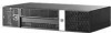
HP Rp3000 Service Reference Guide: HP rp3000 Point of Sale
HP Rp3000 - Point of Sale System Manual
 |
UPC - 884420494096
View all HP Rp3000 manuals
Add to My Manuals
Save this manual to your list of manuals |
HP Rp3000 manual content summary:
- HP Rp3000 | Service Reference Guide: HP rp3000 Point of Sale - Page 1
Service Reference Guide HP rp3000 Point of Sale - HP Rp3000 | Service Reference Guide: HP rp3000 Point of Sale - Page 2
copyright. No part of this document may be photocopied, reproduced, or translated to another language without the prior written consent of Hewlett-Packard Company. Service Reference Guide HP rp3000 Point of Sale Second Edition (December 2009) First Edition (October 2008) Document Part Number: 506599 - HP Rp3000 | Service Reference Guide: HP rp3000 Point of Sale - Page 3
About This Book WARNING! Text set off in this manner indicates that failure to follow directions could result in bodily harm or loss of life. CAUTION: Text set off in this manner indicates that failure to follow directions could result in damage to equipment or loss of information. NOTE: Text set - HP Rp3000 | Service Reference Guide: HP rp3000 Point of Sale - Page 4
iv About This Book - HP Rp3000 | Service Reference Guide: HP rp3000 Point of Sale - Page 5
Device Drivers 1 Downloading Microsoft Windows Updates 2 HP Backup and Recovery Manager ...2 2 Computer Setup (F10) Utility Computer Setup (F10) Utilities ...4 Using Computer Setup (F10) Utilities 5 Computer Setup-File ...6 Computer Setup-Storage 7 Computer Setup-Security 9 Computer Setup-Power - HP Rp3000 | Service Reference Guide: HP rp3000 Point of Sale - Page 6
the Work Area 28 Recommended Materials and Equipment 28 Operating Guidelines ...29 Routine Care ...30 General Cleaning Safety Precautions 30 Cleaning the Computer Case 30 Cleaning the Keyboard ...30 Cleaning the Monitor ...31 Cleaning the Mouse ...31 Service Considerations ...31 Power Supply Fan - HP Rp3000 | Service Reference Guide: HP rp3000 Point of Sale - Page 7
(some models) ...68 Optical Drive Sensor ...69 Power Supply ...70 System Board ...71 Battery ...73 Appendix A Connector Pin Assignments Keyboard ...75 Mouse ...75 Ethernet RJ-45 ...76 RJ-11 ...76 Serial Interface, Powered and Non-Powered 76 USB ...77 Powered USB ...77 Line-in Audio ...77 Line-out - HP Rp3000 | Service Reference Guide: HP rp3000 Point of Sale - Page 8
89 Appendix D Troubleshooting Without Diagnostics Safety and Comfort ...92 Before You Call for Technical Support 92 Helpful Hints ...93 Solving General Problems ...95 Solving Power Problems ...98 Solving Hard Drive Problems ...99 Solving Display Problems ...101 Solving Audio Problems ...105 Solving - HP Rp3000 | Service Reference Guide: HP rp3000 Point of Sale - Page 9
the operating system to the appropriate drivers. Obtain the latest support software, including support software for the operating system from http://www.hp.com/support. Select your country and language, select Download drivers and software (and firmware), enter the model number of the computer, and - HP Rp3000 | Service Reference Guide: HP rp3000 Point of Sale - Page 10
any files or documents that you may have open before rebooting. Then select Yes to reboot the machine. HP Backup and Recovery Manager NOTE: The features described below are only available on systems shipped with Microsoft Windows XP. The HP Backup and Recovery Manager included with Microsoft Windows - HP Rp3000 | Service Reference Guide: HP rp3000 Point of Sale - Page 11
User Guide by selecting Start > HP Backup and Recovery > HP Backup and Recovery Manager Manual. NOTE: You can order a Recovery Disc Set from HP by calling the HP support center. Go to the following Web site, select your region, and click the Technical support after you buy link under the Call HP - HP Rp3000 | Service Reference Guide: HP rp3000 Point of Sale - Page 12
power-on password prompt during system restarts (warm boots) as well as during power-on. ● Establish a setup password that controls access to Computer Setup (F10) Utility and the settings described in this section. ● Secure integrated I/O functionality, including the serial, USB, or parallel ports - HP Rp3000 | Service Reference Guide: HP rp3000 Point of Sale - Page 13
-Storage on page 7 Security Table 2-4 Computer Setup-Security on page 9 Power Table 2-5 Computer Setup-Power on page 11 Advanced Table 2-6 Computer Setup-Advanced (for advanced users) on page 12 NOTE: Support for specific Computer Setup options may vary depending on the hardware configuration - HP Rp3000 | Service Reference Guide: HP rp3000 Point of Sale - Page 14
this listed twice) ● Installed memory size/speed, number of channels (single or dual) (if applicable) ● Integrated MAC address for embedded, enabled NIC (if applicable) ● System BIOS (includes family name and version) ● Chassis serial number ● Asset tracking number About Displays copyright notice - HP Rp3000 | Service Reference Guide: HP rp3000 Point of Sale - Page 15
Automatic, Bit Shift, LBA Assisted, User, and Off. NOTE: If User is selected for the Translation Mode, system or an application) into terms the hard drive can accept. Logical cylinders may not exceed 1024. The number of heads may not exceed 256. The number of sectors per track may not exceed 63. CD - HP Rp3000 | Service Reference Guide: HP rp3000 Point of Sale - Page 16
service ATA disk read and write requests with PIO data transfers. SATA Emulation Allows you to choose how the SATA controller and devices are accessed by the operating system. There are two supported in Boot Order, restart the computer and press F9 when the blue HP logo screen is displayed. After - HP Rp3000 | Service Reference Guide: HP rp3000 Point of Sale - Page 17
Port A ● Serial Port B ● Serial Port C (if an optional serial port expansion card is installed) ● Serial Port D (if an optional serial port expansion card is installed) ● All USB Ports ● System Audio ● Network Controller (some models) Network Service Boot Enables/disables the computer's ability - HP Rp3000 | Service Reference Guide: HP rp3000 Point of Sale - Page 18
that supports the DriveLock feature is attached to the system. See the Desktop Management Guide on the Power-On Password if a Power-On Password is enabled. NOTE: Setup Browse Mode must be set to Enable in order for the user to enter Setup without knowing the setup password. 10 Chapter 2 Computer - HP Rp3000 | Service Reference Guide: HP rp3000 Point of Sale - Page 19
and S5 both have the LED off. S1 (no longer supported) and S3 use 1 blink per second. ● S5 Maximum Power Savings (some models)-Enable/Disable. Enabling this feature reduces the power of this system as much as possible in the S5 state. Power is removed from the wake up circuitry, the expansion slots - HP Rp3000 | Service Reference Guide: HP rp3000 Point of Sale - Page 20
Computer Setup-Advanced Table 2-6 Computer Setup-Advanced (for advanced users) Option Heading 12 Chapter 2 Computer Setup (F10) Utility - HP Rp3000 | Service Reference Guide: HP rp3000 Point of Sale - Page 21
will cause the system to display a message before loading option ROMs. (This feature is supported on some models only.) ● Remote wakeup boot source (remote server/local hard drive). ● After Power Loss (off/on/previous state). If set to Off, the computer remains powered off when power is restored - HP Rp3000 | Service Reference Guide: HP rp3000 Point of Sale - Page 22
the network controller from being used by the operating system and reduces the power used by the computer in S5. ● Processor cache (enable/disable). ● Integrated Video (enable/disable) Allows you to use integrated video and PCI Up Solution video at the same time (available on some models only - HP Rp3000 | Service Reference Guide: HP rp3000 Point of Sale - Page 23
) Utility before Restore is needed. (See Save to Removable Media on page 6 in the Computer Setup-File table.) NOTE: It is recommended that you save any modified computer configuration settings to a a USB flash media device or a diskette-like device (a storage device set to emulate a diskette drive - HP Rp3000 | Service Reference Guide: HP rp3000 Point of Sale - Page 24
on a USB flash drive. Use HP Insight Diagnostics to determine if all the devices installed on the computer are recognized by the system and functioning to the Customer Support Center. NOTE: Third party devices may not be detected by HP Insight Diagnostics. Accessing HP Insight Diagnostics You must - HP Rp3000 | Service Reference Guide: HP rp3000 Point of Sale - Page 25
PCI device information. Asset Control-Shows product name, asset tag, system serial number, and processor information. Communication-Shows information about the computer parallel (LPT) and serial (COM) port settings, plus USB and network controller information. Graphics-Shows information about the - HP Rp3000 | Service Reference Guide: HP rp3000 Point of Sale - Page 26
controller. HP has found through experience that looking at operational history is one of the best ways to diagnose disk drive problems. Systems Insight Manager , but these require user intervention. ● Custom Test-Provides the most flexibility in controlling the testing of a system. The Custom Test - HP Rp3000 | Service Reference Guide: HP rp3000 Point of Sale - Page 27
how you want the test to be executed, either Number of Loops or Total Test Time. When choosing to run the test over a specified number of loops, enter the number of loops to perform. If you desire to have being tested ● The elapsed test times for each device being tested HP Insight Diagnostics 19 - HP Rp3000 | Service Reference Guide: HP rp3000 Point of Sale - Page 28
not save to the hard drive. The system will automatically create an html file that has the same appearance as the information displayed on the screen. 1. Insert a USB 2.0 flash drive (capacity must be 64MB or higher). USB 1.0 flash drives are not supported. 2. Click Save in the bottom right corner - HP Rp3000 | Service Reference Guide: HP rp3000 Point of Sale - Page 29
drive. Downloading the Latest Version of HP Insight Diagnostics 1. Go to http://www.hp.com. 2. Click the Software & Driver Downloads link. 3. Enter your product number (for example, rp3000) in the text box and press the Enter key. 4. Select your specific computer model. 5. Select your OS. 6. Click - HP Rp3000 | Service Reference Guide: HP rp3000 Point of Sale - Page 30
files and folders, operates in Windows®. The second, PC Recovery, requires a reboot to the Recovery Partition or from the Recovery Disc Set. To reboot to the Recovery Partition, press F11 at startup when you see the message Press F11 for Emergency Recovery. 22 Chapter 3 Computer Diagnostic Features - HP Rp3000 | Service Reference Guide: HP rp3000 Point of Sale - Page 31
= SATA Parallel ATA = PATA HP only supports the use of SATA hard drives on these models of computer. No PATA drives are supported on any of these models. SATA Hard Drives Serial ATA Hard Drive Characteristics Number of pins/conductors in data cable Number of pins in power cable Maximum data cable - HP Rp3000 | Service Reference Guide: HP rp3000 Point of Sale - Page 32
. Current HP desktop products and 4 transmit/receive pins. Pin Number Usage P1 Ground P2* A+ P3* power 3.3 V power 3.3 V power 5 V power 5 V power Pin Usage Notes P9 V5 5 V power P10 Ground P11 Ground P12 Ground P13 V12 12 V power P14 V12 12 V power P15 V12 12 V power - HP Rp3000 | Service Reference Guide: HP rp3000 Point of Sale - Page 33
Device Information No PATA drives are supported on any of the rp3000 models. ATA SMART Drives The Self Monitoring Analysis and Recording Technology (SMART) ATA drives for the HP Personal Computers have built-in drive failure prediction that warns the user or network administrator of an impending - HP Rp3000 | Service Reference Guide: HP rp3000 Point of Sale - Page 34
service. CAUTION: When the computer is plugged into an AC power source, voltage is always applied to the system board. You must disconnect the power cord from the power source before opening the computer to prevent system board or component damage. Chassis Designations rp3000 Figure 5-1 rp3000 - HP Rp3000 | Service Reference Guide: HP rp3000 Point of Sale - Page 35
at all and can work perfectly throughout a normal cycle integrated circuits provide some protection, but in many cases, the discharge contains enough power boxes. ● Protect all electrostatic parts and assemblies with conductive or approved containers or packaging. ● Keep electrostatic sensitive parts - HP Rp3000 | Service Reference Guide: HP rp3000 Point of Sale - Page 36
electrostatic sensitive components, parts, and assemblies by the case or PCB laminate. Handle them only at static-free work areas. ● Turn off power and input signals . ● Keep work area free of nonconductive materials such as ordinary plastic assembly aids and Styrofoam. ● Use field service tools, - HP Rp3000 | Service Reference Guide: HP rp3000 Point of Sale - Page 37
floor mats with hard tie to ground ● Field service kits ● Static awareness labels ● Wrist straps and Keep liquids away from the computer and keyboard. ● Never cover the ventilation slots on the monitor with any type of material. ● Install or enable power management functions of the operating system - HP Rp3000 | Service Reference Guide: HP rp3000 Point of Sale - Page 38
solutions to clean the computer. 2. Never immerse any parts in water or cleaning solutions; apply any liquids to a clean cloth and then use the cloth on the component. 3. Always unplug the computer the Computer Case on page 30. When cleaning debris from under the keys, review Disassembly Preparation - HP Rp3000 | Service Reference Guide: HP rp3000 Point of Sale - Page 39
any fibers or dirt in confined areas. Allow the parts to air dry before reassembly. Cleaning the Monitor ● Wipe keep in mind during the disassembly and assembly of the computer. Power Supply Fan The power supply fan is a variable-speed fan based on the temperature in the power supply. The system - HP Rp3000 | Service Reference Guide: HP rp3000 Point of Sale - Page 40
in the computer are not interchangeable. They may have standard or metric threads and may be of different lengths. If an incorrect screw is used during the reassembly process, it can damage the unit. HP strongly recommends that all screws removed during disassembly be kept with the part that was - HP Rp3000 | Service Reference Guide: HP rp3000 Point of Sale - Page 41
Battery The battery that comes with the computer provides power to the real-time clock and has a minimum lifetime of about three years. See the appropriate removal and replacement chapter for the chassis you are working on in this guide for instructions on the replacement procedures. WARNING! This - HP Rp3000 | Service Reference Guide: HP rp3000 Point of Sale - Page 42
present on the system board as long as the system is plugged into an active AC outlet. In some systems the cooling fan is on even when the computer is in the "Standby," or "Suspend" modes. The power cord should always be disconnected before servicing a unit. 6. Disconnect the power cord from the - HP Rp3000 | Service Reference Guide: HP rp3000 Point of Sale - Page 43
External Security Devices The following security devices are used to prevent unauthorized access to the internal components of the computer and/or secure the computer to a fixed object. Cable Lock Figure 6-1 Installing a Cable Lock External Security Devices 35 - HP Rp3000 | Service Reference Guide: HP rp3000 Point of Sale - Page 44
Padlock Figure 6-2 Installing a Padlock HP Business PC Security Lock 1. Fasten the security cable by looping it around a stationary object. Figure 6-3 Securing the Cable to a Fixed Object 36 Chapter 6 Removal and Replacement Procedures - HP Rp3000 | Service Reference Guide: HP rp3000 Point of Sale - Page 45
2. Thread any peripheral device cables that you want to secure through the lock. Figure 6-4 Threading the Peripheral Device Cables 3. Screw the lock to the chassis using the screw provided. Figure 6-5 Attaching the Lock to the Chassis External Security Devices 37 - HP Rp3000 | Service Reference Guide: HP rp3000 Point of Sale - Page 46
sure you closely follow the computer cover removal instructions. 1. Prepare the computer for disassembly (Preparation for Disassembly on page 34). 2. Remove the two screws on the rear of the computer (1) that secure the cover to the computer chassis. 3. Slide the computer cover forward about 1.3 cm - HP Rp3000 | Service Reference Guide: HP rp3000 Point of Sale - Page 47
Bezel Blank 1. Prepare the computer for disassembly (Preparation for Disassembly on page 34). 2. Remove the computer cover (Computer Cover on page 38). 3. Push outward on the two retaining tabs that hold the bezel blank in place (1) then pull the blank inward to remove - HP Rp3000 | Service Reference Guide: HP rp3000 Point of Sale - Page 48
the computer. ● Keep cables away from major heat sources like the heatsink. ● Do not jam cables on top of expansion cards or memory modules. Printed circuit cards like these are not designed to take excessive pressure on them. ● Keep cables clear of movable or rotating parts like the power supply - HP Rp3000 | Service Reference Guide: HP rp3000 Point of Sale - Page 49
find the proper connection. To System board, 24-pin Powered serial port expansion card Powered USB port expansion card 1st SATA Hard drive Optical drive Cable Designator P1 P7 P6 P5 P4 Cable Hard drive Optical drive Serial port, 5V/12V Chassis fan Front power button/LED and Optical drive sensor - HP Rp3000 | Service Reference Guide: HP rp3000 Point of Sale - Page 50
JEDEC SPD information In addition, the computer supports: ● 256Mbit, 512Mbit, and 1Gbit non-ECC memory technologies ● single-sided and double-sided DIMMs ● DIMMs constructed with x8 and x16 DDR devices; DIMMs constructed with x4 SDRAM are not supported NOTE: The system will accept PC2-6400 800 MHz - HP Rp3000 | Service Reference Guide: HP rp3000 Point of Sale - Page 51
modules. Regardless of the power-on state, voltage is always supplied to the memory modules as long as the computer is plugged into an active AC outlet. Adding or removing memory modules while voltage is present may cause irreparable damage to the memory modules or system board. If you see an LED - HP Rp3000 | Service Reference Guide: HP rp3000 Point of Sale - Page 52
! To reduce risk of personal injury from hot surfaces, allow the internal system components to cool before touching. 5. Open both latches of the memory module socket (1), and insert the memory module into the socket (2). NOTE: A memory module can be installed in only one way. Match the notch on the - HP Rp3000 | Service Reference Guide: HP rp3000 Point of Sale - Page 53
drive cage to the down position. 9. Replace the computer cover. 10. Reconnect the power cord and any external devices, then turn on the computer. The computer should automatically recognize the additional memory when you turn on the computer. 11. Lock any security devices that were disengaged when - HP Rp3000 | Service Reference Guide: HP rp3000 Point of Sale - Page 54
3. Remove the screw that secures the expansion card slot cover or the existing expansion card to the chassis. Figure 6-14 Removing the Slot Cover Screw 4. Remove the expansion slot cover or the existing expansion card. a. If you are installing an expansion card in a vacant socket, slide the - HP Rp3000 | Service Reference Guide: HP rp3000 Point of Sale - Page 55
Store the removed card in anti-static packaging. 6. If you are not installing a new expansion card, install an expansion slot cover to close the open slot. CAUTION: After removing an expansion card, you must replace it with a new card or expansion slot cover for proper cooling of internal components - HP Rp3000 | Service Reference Guide: HP rp3000 Point of Sale - Page 56
. Connect internal cables to the system board, if needed. 10. Replace the computer cover. 11. Reconfigure the computer, if necessary. Refer to the Computer Setup (F10) Utility Guide on the Documentation and Diagnostics DVD for instructions about using Computer Setup. PCI Riser Card Cage Assembly - HP Rp3000 | Service Reference Guide: HP rp3000 Point of Sale - Page 57
5. Remove the three screws that secure the riser card assembly to the chassis (1), and then lift the assembly straight up and out of the chassis (2). Figure 6-19 Removing the Riser Card Cage 6. Remove the two screws that secure the PCI riser card to the riser bracket (1), and then remove the card - HP Rp3000 | Service Reference Guide: HP rp3000 Point of Sale - Page 58
USB PlusPower Ports Some models have a PoweredUSB expansion card installed. This card provides one red-colored 24volt PoweredUSB connector (1) and one teal-colored 12-volt PoweredUSB connector (2). NOTE: The rp3000 supports either a ReadyBoost module or a PoweredUSB expansion card, but it will not - HP Rp3000 | Service Reference Guide: HP rp3000 Point of Sale - Page 59
the card up and out of chassis (3). Figure 6-24 Removing the PoweredUSB Expansion Card To install a powered USB card, reverse the installation procedures. NOTE: If there is a panel covering the opening for the ports on the rear of the chassis, you must remove the panel. If a ReadyBoost module is - HP Rp3000 | Service Reference Guide: HP rp3000 Point of Sale - Page 60
standard on the computer. Some models have a powered serial port expansion card installed that supplies two additional powered serial ports, COM 3 and COM 4. Figure 6-25 Powered Serial Ports Item Description 1 COM 1 2 COM 2 3 COM 3 (some models) 4 COM 4 (some models) Supports +5V Yes Yes - HP Rp3000 | Service Reference Guide: HP rp3000 Point of Sale - Page 61
Power to a Serial Port The serial ports on the HP Point of Sale System computer can be configured as standard (non-powered) serial ports or powered serial ports. Some Point of Sale devices use a powered serial port. If the serial port is configured as a powered port, devices that support a powered - HP Rp3000 | Service Reference Guide: HP rp3000 Point of Sale - Page 62
Figure 6-27 Serial Port Jumper Locations on the System Board Item 1 2 Jumper P16 P17 Port Name COM 1 COM 2 The serial port jumpers on the powered serial port expansion card are located as shown in the following illustration: Figure 6-28 Powered Serial Port Expansion Card Jumper Locations Item 1 - HP Rp3000 | Service Reference Guide: HP rp3000 Point of Sale - Page 63
To configure power to the serial ports: 1. Prepare the computer for disassembly (Preparation for Disassembly on page 34). 2. Remove the computer cover (Computer Cover on page 38). 3. If you are changing the system board COM 1 or COM 2 serial port configuration: a. Raise the drive cage to the upright - HP Rp3000 | Service Reference Guide: HP rp3000 Point of Sale - Page 64
until the connectors pull free from the socket (2). Be sure not to scrape the card against the other components. Figure 6-30 Removing the Powered Serial Port Expansion Card c. Place jumpers and jumper wires on the appropriate pins for COM 3 (1) and COM 4 (2). Figure 6-31 COM 3 and COM 4 Jumpers 56 - HP Rp3000 | Service Reference Guide: HP rp3000 Point of Sale - Page 65
Figure 6-33 Connecting Data and Power Cables to the Powered Serial Port Expansion Card 5. Replace the computer cover. 6. If the serial ports are configured in powered mode, connect the powered Point of Sale device. HP offers two preconfigured serial port jumper configurations by selecting one of - HP Rp3000 | Service Reference Guide: HP rp3000 Point of Sale - Page 66
then be selected so all four serial ports are configured for power. Below is a diagram showing the jumper settings for each of these optional preconfigured AV numbers: CAUTION: Always unplug the rp3000 from power when configuring jumpers. rp3000 motherboard: Serial/COM 1 - P16, Serial/COM 2 = P17 - HP Rp3000 | Service Reference Guide: HP rp3000 Point of Sale - Page 67
GND, so when the ports are configured for power, it is possible to short power to GND if something comes in contact with the shell and pin. These AV's include COM port cover to help prevent this. AVs GH655AV GH656AV Description Service Preconfig 2x PWRD RS232 5V/12V Service Preconfig 4x PWRD RS232 - HP Rp3000 | Service Reference Guide: HP rp3000 Point of Sale - Page 68
the Computer Setup (F10) Utility Guide on the Documentation and Diagnostics DVD for more information. Installing and Removing Drives When installing additional drives, follow these guidelines: ● The primary Serial ATA (SATA) hard drive must be connected to the dark blue SATA connector on the system - HP Rp3000 | Service Reference Guide: HP rp3000 Point of Sale - Page 69
screws to ensure the drive will be locked in place. HP has provided eight extra retainer screws if needed. Four of the a drive, shut down the operating system properly, turn off the computer, and unplug the power cord. Do not remove a drive while the computer is on or in standby mode. Before - HP Rp3000 | Service Reference Guide: HP rp3000 Point of Sale - Page 70
drive is a CD-ROM, CD-R/RW, DVD-ROM, DVD+R/RW, or CD-RW/DVD Combo drive. 1. Prepare the computer for disassembly (Preparation for Disassembly on page 34). 2. Remove the computer cover (Computer Cover on page 38). 3. Raise the drive cage to the upright position. 4. Disconnect the power cable (1) and - HP Rp3000 | Service Reference Guide: HP rp3000 Point of Sale - Page 71
Figure 6-39 Connecting the Optical Drive Power and Data Cables CAUTION: Never crease or bend a SATA data cable tighter than a 30 mm (1.18 in) radius. A sharp bend can break the internal wires. 5. Connect the other end of the SATA data cable to the white system board connector labeled SATA 1. Drives - HP Rp3000 | Service Reference Guide: HP rp3000 Point of Sale - Page 72
3.5-inch Internal Hard Drive 1. Prepare the computer for disassembly (Preparation for Disassembly on page 34). 2. Remove the computer cover (Computer Cover on page 38). 3. Raise the drive cage to the upright position. 4. Disconnect the data cable (1) and power cable (2) from the back of the primary - HP Rp3000 | Service Reference Guide: HP rp3000 Point of Sale - Page 73
the hard drive bay in the drive cage so that the bottom of the hard drive is next to the optical drive compartment and the power and data connectors are up. Slide the drive all the way down into the drive cage until it stops. Figure 6-43 Installing the Hard Drive - HP Rp3000 | Service Reference Guide: HP rp3000 Point of Sale - Page 74
drive. NOTE: The data cable must be connected to the dark blue connector labeled SATA 0 on the system board to avoid any hard drive performance problems. Figure 6-45 Connecting the Hard Drive Data and Power Cables CAUTION: Never crease or bend a SATA data cable tighter than a 30 mm (1.18 in) radius - HP Rp3000 | Service Reference Guide: HP rp3000 Point of Sale - Page 75
operating system, software drivers, and any software applications that were preinstalled on the computer. When Power Switch/LED Assembly 1. Prepare the computer for disassembly (Preparation for Disassembly on page 34). 2. Remove the computer cover (Computer Cover on page 38). 3. Position the computer - HP Rp3000 | Service Reference Guide: HP rp3000 Point of Sale - Page 76
assembly from the system board. 8. Remove the assembly from the chassis. To reinstall the power switch/LED assembly, reverse the removal procedure. Modem (some models) 1. Prepare the computer for disassembly (Preparation for Disassembly on page 34). 2. Remove the computer cover (Computer Cover on - HP Rp3000 | Service Reference Guide: HP rp3000 Point of Sale - Page 77
on the system board. computer for disassembly (Preparation for Disassembly on page 34). 2. Remove the computer cover (Computer Cover on page 38). CAUTION: To reduce risk of damage to optical door sensor, make sure you closely follow the computer cover removal instructions. 3. Position the computer - HP Rp3000 | Service Reference Guide: HP rp3000 Point of Sale - Page 78
on the system board when the computer is plugged into an active AC outlet. To avoid possible personal injury and damage to the equipment the power cord should be disconnected from the computer and/or the AC outlet before opening the computer. 1. Prepare the computer for disassembly (Preparation for - HP Rp3000 | Service Reference Guide: HP rp3000 Point of Sale - Page 79
installing the power supply cables, make sure they are properly positioned so they are not cut by the drive cage. System Board 1. Prepare the computer for disassembly (Preparation for Disassembly on page 34). 2. Remove the computer cover (Computer Cover on page 38). 3. Position the computer with the - HP Rp3000 | Service Reference Guide: HP rp3000 Point of Sale - Page 80
up to disengage it from the connectors, slide it away from the power supply, and then lift it up and out of the chassis. Figure 6-53 Removing the System Board To install the system board, reverse the removal procedure. CAUTION: When reconnecting the cables it is important that they be positioned - HP Rp3000 | Service Reference Guide: HP rp3000 Point of Sale - Page 81
connected to AC power. HP encourages customers to recycle used electronic hardware, HP original print cartridges, and rechargeable batteries. For more information about recycling programs, go to http://www.hp.com/ recycle. 1. Prepare the computer for disassembly (Preparation for Disassembly on page - HP Rp3000 | Service Reference Guide: HP rp3000 Point of Sale - Page 82
to the down position. 8. Replace the computer cover. 9. Plug in the computer and turn on power to the computer. 10. Reset the date and time, your passwords, and any special system setups using Computer Setup. Refer to the Computer Setup (F10) Utility Guide on the Documentation and Diagnostics DVD - HP Rp3000 | Service Reference Guide: HP rp3000 Point of Sale - Page 83
A Connector Pin Assignments This appendix contains the pin assignments for many computer and workstation connectors. Some of these connectors may not be used on the product being serviced. Keyboard Connector and Icon Pin Signal 1 Data 2 Unused 3 Ground 4 +5 VDC 5 Clock 6 Unused - HP Rp3000 | Service Reference Guide: HP rp3000 Point of Sale - Page 84
8 Unused Pin Signal 1 Unused 2 Tip 3 Ring 4 Unused 5 Unused 6 Unused Serial Interface, Powered and Non-Powered Connector and Icon Pin Signal 1 Carrier Detect (5V/12V if powered) 2 Receive Data 3 Transmit Data 4 Data Terminal Ready 5 Signal Ground 6 Data Set Ready - HP Rp3000 | Service Reference Guide: HP rp3000 Point of Sale - Page 85
Connector and Icon Powered USB Connector and Icon Line-in Audio Connector and Icon (1/8" miniphone) 1 23 Line-out Audio Connector and Icon (1/8" ) 2 (Ring) 3 (Shield) Signal Audio_In_Left Audio_In_Right Ground Pin 1 (Tip) 2 (Ring) 3 (Shield) Signal Audio_Out_Left Audio_Out_Right Ground USB 77 - HP Rp3000 | Service Reference Guide: HP rp3000 Point of Sale - Page 86
Ground 11 Not used 12 DDC Serial Data 13 Horizontal Sync 14 Vertical Sync 15 DDC Serial Clock 24-Pin Power Connector 24 12 Pin Signal 1 +3.3V 2 +3.3V 3 GND 4 +5V 5 GND 6 +5V 13 Pin Signal 19 GND 20 open 21 +5V 22 +5V 23 +5V 24 GND 78 Appendix A Connector Pin Assignments - HP Rp3000 | Service Reference Guide: HP rp3000 Point of Sale - Page 87
Drive Connector Pin Signal S1 Ground S5 BP1 Ground P5 BP9 V 5 P13 V 12 *S = Data, P = Power Pin Signal S2 A+ S6 B+ P2 V 3.3 P6 Ground P10 Ground P14 V12 PCI Express, Pin A x1, x4, x8, and x16 PCI Express PERn1 23 GND 24 GND 25 PERp2 46 GND 47 PERp7 48 PERn7 49 GND 50 RSVD SATA Data and Power 79 - HP Rp3000 | Service Reference Guide: HP rp3000 Point of Sale - Page 88
51 GND 56 PERp9 52 PERp8 57 PERn9 53 PERN8 58 GND 54 GND 59 GND 55 GND 60 PERp10 76 PERp14 81 PERn15 77 PERn14 82 GND 78 GND 79 GND 80 PERp15 Pin B information is in the next table NOTE: x1 PCI Express uses pins 1-18 x4 PCI Express uses pins 1-32 x8 PCI Express uses pins 1-49 - HP Rp3000 | Service Reference Guide: HP rp3000 Point of Sale - Page 89
26 GND 31 PRSNT2# 27 PETp3 32 GND 28 PETn3 33 PETp4 29 GND 34 PETn4 30 RSVD 35 GND 51 PETn8 56 GND 52 GND 57 GND 53 GND 58 PETp10 54 PETp9 59 PETn10 55 PETn9 60 GND 76 GND 81 PRSNT2# 77 GND 82 RSVD 78 PETp15 79 PETn15 80 GND Pin A information is in the previous table NOTE - HP Rp3000 | Service Reference Guide: HP rp3000 Point of Sale - Page 90
B Power Cord Set Requirements The power supplies on some computers have external power switches. The voltage select switch feature on the computer permits it to operate from any line voltage between 100-120 or 220-240 volts AC. Power supplies on those computers that do not have external power - HP Rp3000 | Service Reference Guide: HP rp3000 Point of Sale - Page 91
must be Type HO5VV-F, 3-conductor, 0.75mm2 conductor size. Power cord set fittings (appliance coupler and wall plug) must bear Appliance coupler, flexible cord, and wall plug must bear a "T" mark and registration number in accordance with the Japanese Dentori Law. Flexible cord must be Type VCT or - HP Rp3000 | Service Reference Guide: HP rp3000 Point of Sale - Page 92
sequences that you may encounter during Power-On Self-Test (POST) or computer restart, the probable source of the problem, and steps you can take to resolve the error condition. POST Message Disabled suppresses most system messages during POST, such as memory count and non-error text messages - HP Rp3000 | Service Reference Guide: HP rp3000 Point of Sale - Page 93
/USB Buffers @ Top of Memory setting in Computer Setup is enabled. 162-System Computer Setup and check the configuration in Advanced > Onboard Devices. Reset the date and time under Control Panel. If the problem persists, replace the RTC battery. See the Hardware Reference Guide for instructions - HP Rp3000 | Service Reference Guide: HP rp3000 Point of Sale - Page 94
time or date in configuration memory. RTC (real-time clock) battery may need to be replaced. Reset the date and time under Control Panel (Computer Setup can also be used). If the problem persists, replace the RTC battery. See the Hardware Reference Guide for instructions on installing a new battery - HP Rp3000 | Service Reference Guide: HP rp3000 Point of Sale - Page 95
Determine if hard drive is giving correct error message. Enter Computer Setup and run the Drive Protection System test under Storage > DPS Self-test. 2. Apply hard drive firmware patch if applicable. (Available at http://www.hp.com/support.) 3. Back up contents and replace hard drive. 1796-SATA - HP Rp3000 | Service Reference Guide: HP rp3000 Point of Sale - Page 96
to be entered, download the executable file from http://www.hp.com. 2. Run Computer Setup and try to enter serial number under Security, System ID, then save changes. Memory Parity Error Parity RAM failure. Run Computer Setup and Diagnostic utilities. Third-party graphics card may be causing - HP Rp3000 | Service Reference Guide: HP rp3000 Point of Sale - Page 97
continue until problem is solved. Power failure (power supply is overloaded). 4. Contact an authorized reseller or service provider. 1. Check if a device is causing the problem by removing ALL attached devices (such as hard drives, optical drives, and expansion cards). Power on the system. If the - HP Rp3000 | Service Reference Guide: HP rp3000 Point of Sale - Page 98
by a two second pause. Beeps stop after fifth iteration but LEDs continue until problem is solved. Pre-video memory error. CAUTION: To avoid damage to the DIMMs or the system board, you must unplug the computer power cord before attempting to reseat, install, or remove a DIMM. 1. Reseat DIMMs - HP Rp3000 | Service Reference Guide: HP rp3000 Point of Sale - Page 99
3. Check that the power supply cable is properly connected to the system board. 4. Check to see if the LED on the system board is turned on. If it is turned on, then replace the power button harness. If the problem persists, replace the system board. 5. If the LED on the system board is not turned - HP Rp3000 | Service Reference Guide: HP rp3000 Point of Sale - Page 100
Refer to the Safety & Comfort Guide at http://www.hp.com/ ergo for more information on choosing a workspace and creating a safe and comfortable work environment. Before You Call for Technical Support If you are having problems with the computer, try the appropriate solutions below to try to isolate - HP Rp3000 | Service Reference Guide: HP rp3000 Point of Sale - Page 101
when you call. ● Write down the computer serial number and product ID number, and the monitor serial number before calling. ● Spend time troubleshooting the problem with the service technician. ● Remove any hardware that was recently added to your system. ● Remove any software that was recently - HP Rp3000 | Service Reference Guide: HP rp3000 Point of Sale - Page 102
Solving Hardware Installation Problems on page 109 for instructions. ● Be sure that all the needed device drivers have been installed. For example, if you are using a printer, you need a driver for that model printer. ● Remove all bootable media (CD or USB device) from the system before turning it - HP Rp3000 | Service Reference Guide: HP rp3000 Point of Sale - Page 103
the LED is illuminated, the system still has power. Power off the computer and remove the power cord before proceeding. Table D-1 Solving General Problems Computer appears locked up and will not turn off when the power button is pressed. Cause Solution Software control of the power switch is not - HP Rp3000 | Service Reference Guide: HP rp3000 Point of Sale - Page 104
consult the documentation that came with the application for suggestions on how to improve performance by adjusting parameters in the application. 2. Add more memory. 3. Upgrade the graphics solution. Cause unknown. Restart the computer. 96 Appendix D Troubleshooting Without Diagnostics - HP Rp3000 | Service Reference Guide: HP rp3000 Point of Sale - Page 105
replace the power supply. 6. Replace the system board. DVD or CD in the optical drive will not eject. Cause The sliding door that covers the optical drive is closed. Solution Use the key provided to unlock the door (if necessary) and slide the door all the way down. Solving General Problems 97 - HP Rp3000 | Service Reference Guide: HP rp3000 Point of Sale - Page 106
the fan assembly. 4. Contact an authorized reseller or service provider. Powered POS peripherals do not power on. Cause Power supply cable not connected to powered USB card. Solution Make sure power supply cable is connected to powered USB card. 98 Appendix D Troubleshooting Without Diagnostics - HP Rp3000 | Service Reference Guide: HP rp3000 Point of Sale - Page 107
computer beeps four times. (Beeps stop after fifth iteration but LEDs continue flashing.) Cause Solution Power failure (power supply is overloaded). 1. Open the hood and ensure the power supply cable is seated into the connector on the system board. 2. Check if a device is causing the problem - HP Rp3000 | Service Reference Guide: HP rp3000 Point of Sale - Page 108
responds slowly immediately after power-up. Run Computer Setup and increase the POST Delay in Advanced > Power-On Options. Nonsystem disk/NTLDR missing message. Cause Solution The system is trying to start from the hard drive but the hard 1. Insert a bootable CD or USB device and restart the - HP Rp3000 | Service Reference Guide: HP rp3000 Point of Sale - Page 109
the computer, press the power button again. Solving Display Problems If you encounter display problems, see the documentation that came with the monitor and the common causes and solutions listed in the following table. Table D-4 Solving Display Problems Blank screen (no video). Cause Solution - HP Rp3000 | Service Reference Guide: HP rp3000 Point of Sale - Page 110
-party memory with HP memory. 4. Replace the system board. Blank screen and the power LED flashes Red six times, once every second, followed by a two second pause, and the computer beeps six times. (Beeps stop after fifth iteration but LEDs continue flashing.) Cause Solution Pre-video graphics - HP Rp3000 | Service Reference Guide: HP rp3000 Point of Sale - Page 111
Table D-4 Solving Display Problems (continued) Blank screen and the power LED flashes Red seven times, once every second, followed by a two second pause, and the computer beeps seven times. (Beeps stop after fifth iteration but LEDs continue flashing.) Cause Solution System board failure (ROM - HP Rp3000 | Service Reference Guide: HP rp3000 Point of Sale - Page 112
that the computer power is off while connecting the video cable. "Out of Range" displays on screen. Cause Solution Video resolution and refresh rate are set higher than what the Restart the computer and enter Safe Mode. Change the monitor supports. settings to a supported setting then restart - HP Rp3000 | Service Reference Guide: HP rp3000 Point of Sale - Page 113
. Click Start > All Programs > Accessories > System Tools > Character Map. You can copy the symbol from the Character Map into a document. Solving Audio Problems If the computer has audio features and you encounter audio problems, see the common causes and solutions listed in the following table - HP Rp3000 | Service Reference Guide: HP rp3000 Point of Sale - Page 114
data. Computer appears to be locked up while recording audio. Cause Solution The hard disk may be full. Before recording, make sure there is enough free space on the hard disk. You can also try recording the audio file in a compressed format. 106 Appendix D Troubleshooting Without Diagnostics - HP Rp3000 | Service Reference Guide: HP rp3000 Point of Sale - Page 115
and check the power cord and electrical outlet. Printer prints garbled information. Cause The correct printer driver for the application is not installed. The cables may not be connected properly. Printer memory may be overloaded. Solution Install the correct printer driver for the application - HP Rp3000 | Service Reference Guide: HP rp3000 Point of Sale - Page 116
attempting to resume from standby mode, do not hold down the power button for more than four seconds. Otherwise, the computer will shut down and you will lose any unsaved data. Cursor will not move using the arrow keys on the keypad. Cause Solution The Num Lock key may be on. Press the Num - HP Rp3000 | Service Reference Guide: HP rp3000 Point of Sale - Page 117
and configures the computer. If you install a non-plug and play device, you must reconfigure the computer after completing installation of the new hardware. In Windows, use the Add Hardware Wizard and follow the instructions that appear on the screen. Solving Hardware Installation Problems 109 - HP Rp3000 | Service Reference Guide: HP rp3000 Point of Sale - Page 118
Setup (F10) and enable the USB ports in Security > Device Security. Computer will not start. Cause Solution Wrong memory modules were used in the upgrade or memory 1. modules were installed in the wrong location. Review the documentation that came with the system to determine if you are using - HP Rp3000 | Service Reference Guide: HP rp3000 Point of Sale - Page 119
. 3. Replace third-party memory with HP memory. 4. Replace the system board. Power LED flashes Red six times, once every second, followed by a two second pause, and the computer beeps six times. (Beeps stop after fifth iteration but LEDs continue flashing.) Cause Solution Graphics card (if - HP Rp3000 | Service Reference Guide: HP rp3000 Point of Sale - Page 120
Configure. 6. Click the Power Management tab, then select the check box to Allow this device to bring the computer out of standby. Network driver does not detect network controller. Cause Network controller is disabled. Incorrect network driver. Solution 1. Run Computer Setup and enable network - HP Rp3000 | Service Reference Guide: HP rp3000 Point of Sale - Page 121
NIC. Under the Computer Setup Advanced menu, change the resource settings for the board. Network controller stops working without apparent cause. Cause Solution The files containing the network drivers are corrupted. Download the network drivers from http://www.hp.com and reinstall them - HP Rp3000 | Service Reference Guide: HP rp3000 Point of Sale - Page 122
an authorized service provider. Solving Memory Problems If you encounter memory problems, some common causes and solutions are listed in the following table. CAUTION: Power may still be supplied to the DIMMs when the computer is turned off. To avoid damage to the DIMMs or the system board, you - HP Rp3000 | Service Reference Guide: HP rp3000 Point of Sale - Page 123
or is bad. 1. Reseat DIMMs. Power on the system. 2. Replace DIMMs one at a time to isolate the faulty module. 3. Replace third-party memory with HP memory. 4. Replace the system board. Solving Processor Problems If you encounter processor problems, common causes and solutions are listed in the - HP Rp3000 | Service Reference Guide: HP rp3000 Point of Sale - Page 124
Setup. If it is listed, the probable cause is a driver problem. If it is not listed, the probable cause is a hardware problem. If this is a newly installed drive, run the Computer Setup utility and try adding a POST delay under Advanced > Power-On Options. The SATA controller has been disabled in - HP Rp3000 | Service Reference Guide: HP rp3000 Point of Sale - Page 125
to remove or uninstall the device. 2. Restart the computer and let Windows detect the CD or DVD driver. Recording or copying CDs is difficult or impossible. Cause Wrong or poor quality media type. Solution 1. Try using a slower speed when recording. 2. Verify that you are using the correct media - HP Rp3000 | Service Reference Guide: HP rp3000 Point of Sale - Page 126
Sliding door that covers the optical drive will not open. Cause The sliding door is locked. Solution Use the provided key to unlock the door then slide the door down. 118 Appendix D Troubleshooting Without Diagnostics - HP Rp3000 | Service Reference Guide: HP rp3000 Point of Sale - Page 127
in the "Replicating the Setup" section of the Service Reference Guide. The computer boots to DOS after making a bootable USB flash drive. Cause Solution USB flash drive is bootable. Install the USB flash drive only after the operating system boots. Solving USB Flash Drive Problems 119 - HP Rp3000 | Service Reference Guide: HP rp3000 Point of Sale - Page 128
solutions listed in the following table. Table D-15 Solving Internet Access Problems Unable to connect to the Internet. Cause Solution Internet Service UTP cable between the cable modem and the computers's RJ-45 connector. (If the connection is good, the "PC" LED light on the front of the cable - HP Rp3000 | Service Reference Guide: HP rp3000 Point of Sale - Page 129
the application. ● There is a conflict between applications. ● Be sure that all the needed device drivers have been installed. ● If you have installed an operating system other than the factory-installed operating system, check to be sure it is supported on the system. Solving Software Problems 121 - HP Rp3000 | Service Reference Guide: HP rp3000 Point of Sale - Page 130
computer to an authorized reseller, dealer, or service provider for service, remember to provide the setup and power-on passwords if they are set. Refer to the number listed in the warranty or in the Support Telephone Numbers guide for technical assistance. 122 Appendix D Troubleshooting Without - HP Rp3000 | Service Reference Guide: HP rp3000 Point of Sale - Page 131
100-240 VAC Rated Line Frequency 50-60 Hz 50-60 Hz Power Output 150 W 150 W Rated Input Current (maximum)1 3A @ 90 VAC 1.5A @ 180 VAC 1 This system utilizes an active power factor corrected power supply. This allows the system to pass the CE mark requirements for use in the countries of - HP Rp3000 | Service Reference Guide: HP rp3000 Point of Sale - Page 132
cover locking and unlocking 35 computer cover, SFF removal and replacement 38 connections SFF system board 41 connector pin assignments 75 country power cord set requirements 83 Customer Support 92, 122 D diagnostics utility 16 DIMMs. See memory disassembly preparation SFF 34 drive SFF optical - HP Rp3000 | Service Reference Guide: HP rp3000 Point of Sale - Page 133
country specific 83 power problems 98 power supply fan 31 removal and replacement 70 power switch/LED assembly removal and replacement 67 powered serial ports configuring 53 expansion card jumpers 54 removing caps 53 system board jumpers 53 printer problems 107 problems audio 105 CD-ROM or DVD - HP Rp3000 | Service Reference Guide: HP rp3000 Point of Sale - Page 134
specifications computer 123 memory 42 static electricity 27 system board removal and replacement 71 SATA connectors 23 T tamper-proof screws tool 32 temperature control 29 tools, servicing 31 Torx T15 screwdriver 31 U unlocking computer cover 35 USB flash drive problems 119 USB pin assignments 77 V
-
 1
1 -
 2
2 -
 3
3 -
 4
4 -
 5
5 -
 6
6 -
 7
7 -
8
-
9
-
10
-
11
-
12
-
13
-
14
-
15
-
16
-
17
-
18
-
19
-
20
-
21
-
22
-
23
-
24
-
25
-
26
-
27
-
28
-
29
-
30
-
31
-
32
-
33
-
34
-
35
-
36
-
37
-
38
-
39
-
40
-
41
-
42
-
43
-
44
-
45
-
46
-
47
-
48
-
49
-
50
-
51
-
52
-
53
-
54
-
55
-
56
-
57
-
58
-
59
-
60
-
61
-
62
-
63
-
64
-
65
-
66
-
67
-
68
-
69
-
70
-
71
-
72
-
73
-
74
-
75
-
76
-
77
-
78
-
79
-
80
-
81
-
82
-
83
-
84
-
85
-
86
-
87
-
88
-
89
-
90
-
91
-
92
-
93
-
94
-
95
-
96
-
97
-
98
-
99
-
100
-
101
-
102
-
103
-
104
-
105
-
106
-
107
-
108
-
109
-
110
-
111
-
112
-
113
-
114
-
115
-
116
-
117
-
118
-
119
-
120
-
121
-
122
-
123
-
124
-
125
-
126
-
127
-
128
-
129
-
130
-
131
-
132
-
133
-
134
 |
 |

Service Reference Guide
HP rp3000 Point of Sale