HP Rp3000 Service Reference Guide: HP rp3000 Point of Sale - Page 74
CAUTION, Connecting the Hard Drive Data and Power Cables
 |
UPC - 884420494096
View all HP Rp3000 manuals
Add to My Manuals
Save this manual to your list of manuals |
Page 74 highlights
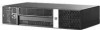
3. Replace the four screws on top of the drive cage that secure the hard drive in the bay. NOTE: You must hold the hard drive in place with one hand while installing the screws to ensure that the screw holes on the hard drive are properly aligned with the screw holes on the drive cage. Figure 6-44 Replacing the Hard Drive Retainer Screws 4. Connect the data cable (1) and power cable (2) to the back of the primary hard drive. NOTE: The data cable must be connected to the dark blue connector labeled SATA 0 on the system board to avoid any hard drive performance problems. Figure 6-45 Connecting the Hard Drive Data and Power Cables CAUTION: Never crease or bend a SATA data cable tighter than a 30 mm (1.18 in) radius. A sharp bend can break the internal wires. 5. Return the drive cage to the down position. 6. Replace the computer cover. 66 Chapter 6 Removal and Replacement Procedures
-
 1
1 -
2
-
3
-
4
-
5
-
6
-
7
-
8
-
9
-
10
-
11
-
12
-
13
-
14
-
15
-
16
-
17
-
18
-
19
-
20
-
21
-
22
-
23
-
24
-
25
-
26
-
27
-
28
-
29
-
30
-
31
-
32
-
33
-
34
-
35
-
36
-
37
-
38
-
39
-
40
-
41
-
42
-
43
-
44
-
45
-
46
-
47
-
48
-
49
-
50
-
51
-
52
-
53
-
54
-
55
-
56
-
57
-
58
-
59
-
60
-
61
-
62
-
63
-
64
-
65
-
66
-
67
-
68
-
 69
69 -
 70
70 -
 71
71 -
 72
72 -
 73
73 -
 74
74 -
 75
75 -
 76
76 -
 77
77 -
 78
78 -
 79
79 -
80
-
81
-
82
-
83
-
84
-
85
-
86
-
87
-
88
-
89
-
90
-
91
-
92
-
93
-
94
-
95
-
96
-
97
-
98
-
99
-
100
-
101
-
102
-
103
-
104
-
105
-
106
-
107
-
108
-
109
-
110
-
111
-
112
-
113
-
114
-
115
-
116
-
117
-
118
-
119
-
120
-
121
-
122
-
123
-
124
-
125
-
126
-
127
-
128
-
129
-
130
-
131
-
132
-
133
-
134
 |
 |
