HP Rp3000 Service Reference Guide: HP rp3000 Point of Sale - Page 79
System Board, CAUTION
 |
UPC - 884420494096
View all HP Rp3000 manuals
Add to My Manuals
Save this manual to your list of manuals |
Page 79 highlights
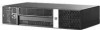
8. Remove the silver T15 screw on the side of the power supply on the inside of the chassis that secures it to the base pan. Figure 6-52 Removing the Inner Power Supply Screw 9. Lift up slightly on the front of the power supply, and then slide it forward so the power connector lip on the back of the power supply clears the slot in the chassis. Then lift the rear of the power supply up at an angle, and then lift the power supply up and out of the unit. To install the power supply, reverse the removal procedure. CAUTION: When installing the power supply cables, make sure they are properly positioned so they are not cut by the drive cage. System Board 1. Prepare the computer for disassembly (Preparation for Disassembly on page 34). 2. Remove the computer cover (Computer Cover on page 38). 3. Position the computer with the rear facing toward you. 4. Rotate the drive cage to its full upright position. 5. Remove the expansion board installed on the system board (Expansion Cards on page 45). -orRemove the riser card cage PCI Riser Card Cage Assembly on page 48. 6. Remove the powered USB assembly (USB PlusPower Ports on page 50). 7. Remove the chassis fan from the chassis Chassis Fan on page 67 8. Disconnect all remaining data and power cables from the system board. 9. Remove the nine screws that secure the system board to the floor of the chassis. System Board 71
-
 1
1 -
2
-
3
-
4
-
5
-
6
-
7
-
8
-
9
-
10
-
11
-
12
-
13
-
14
-
15
-
16
-
17
-
18
-
19
-
20
-
21
-
22
-
23
-
24
-
25
-
26
-
27
-
28
-
29
-
30
-
31
-
32
-
33
-
34
-
35
-
36
-
37
-
38
-
39
-
40
-
41
-
42
-
43
-
44
-
45
-
46
-
47
-
48
-
49
-
50
-
51
-
52
-
53
-
54
-
55
-
56
-
57
-
58
-
59
-
60
-
61
-
62
-
63
-
64
-
65
-
66
-
67
-
68
-
69
-
70
-
71
-
72
-
73
-
 74
74 -
 75
75 -
 76
76 -
 77
77 -
 78
78 -
 79
79 -
 80
80 -
 81
81 -
 82
82 -
 83
83 -
 84
84 -
85
-
86
-
87
-
88
-
89
-
90
-
91
-
92
-
93
-
94
-
95
-
96
-
97
-
98
-
99
-
100
-
101
-
102
-
103
-
104
-
105
-
106
-
107
-
108
-
109
-
110
-
111
-
112
-
113
-
114
-
115
-
116
-
117
-
118
-
119
-
120
-
121
-
122
-
123
-
124
-
125
-
126
-
127
-
128
-
129
-
130
-
131
-
132
-
133
-
134
 |
 |
