IBM 8863 Service Guide - Page 73
Diagnostic, programs, messages, error, codes
 |
UPC - 000435474667
View all IBM 8863 manuals
Add to My Manuals
Save this manual to your list of manuals |
Page 73 highlights
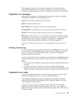
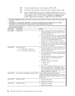
v Follow the suggested actions in the order in which they are listed in the Action column until the problem is solved. v See Chapter 3, "Parts listing, Type 8863," on page 93 to determine which components are customer replaceable units (CRU) and which components are field replaceable units (FRU). v If an action step is preceded by "(Trained service technician only)", that step must be performed only by a trained service technician. Power-supply LEDs AC good DC good Operator information panel power LED Description Action Off Off Off No power to the 1. Check the ac power to the server. server, or a problem with the ac power source. 2. Make sure that the power cord is connected to a functioning power source. 3. Remove one power supply at a time. Lit Off Off DC source power 1. Make sure that the microprocessor tray is connected problem to the power backplane. 2. Remove one power supply at a time. 3. View the system-error log (see "Error logs" on page 18). Lit Lit Off Standby power problem 1. View the system-error log (see "Error logs" on page 18). 2. Isolate by removing one power supply at a time. 3. (Trained service technician only) Replace the power backplane. Lit Lit Flashing System power-on 1. View the system-error log (see "Error logs" on page problem 18). 2. Press the power-control button on the operator information panel. 3. (Trained service technician only) Use the force-power-on jumper as a debugging aid (see "I/O board internal connectors and jumpers" on page 8) to determine whether the information panel switch and cable are faulty. 4. Remove the optional Remote Supervisor Adapter II SlimLine, and try to turn on the server. 5. Reseat the microprocessor tray. 6. (Trained service technician only) Replace the microprocessor tray. Lit Lit Lit The power is good. No action. Diagnostic programs, messages, and error codes The server diagnostic programs are the primary method of testing the major components of the server. As you run the diagnostic programs, text messages and error codes are displayed on the screen and are saved in the test log. A diagnostic text message or error code indicates that a problem has been detected; to determine what action you should take as a result of a message or error code, see the table in "Diagnostic error codes" on page 59. Chapter 2. Diagnostics 57
-
 1
1 -
2
-
3
-
4
-
5
-
6
-
7
-
8
-
9
-
10
-
11
-
12
-
13
-
14
-
15
-
16
-
17
-
18
-
19
-
20
-
21
-
22
-
23
-
24
-
25
-
26
-
27
-
28
-
29
-
30
-
31
-
32
-
33
-
34
-
35
-
36
-
37
-
38
-
39
-
40
-
41
-
42
-
43
-
44
-
45
-
46
-
47
-
48
-
49
-
50
-
51
-
52
-
53
-
54
-
55
-
56
-
57
-
58
-
59
-
60
-
61
-
62
-
63
-
64
-
65
-
66
-
67
-
 68
68 -
 69
69 -
 70
70 -
 71
71 -
 72
72 -
 73
73 -
 74
74 -
 75
75 -
 76
76 -
 77
77 -
 78
78 -
79
-
80
-
81
-
82
-
83
-
84
-
85
-
86
-
87
-
88
-
89
-
90
-
91
-
92
-
93
-
94
-
95
-
96
-
97
-
98
-
99
-
100
-
101
-
102
-
103
-
104
-
105
-
106
-
107
-
108
-
109
-
110
-
111
-
112
-
113
-
114
-
115
-
116
-
117
-
118
-
119
-
120
-
121
-
122
-
123
-
124
-
125
-
126
-
127
-
128
-
129
-
130
-
131
-
132
-
133
-
134
-
135
-
136
-
137
-
138
-
139
-
140
-
141
-
142
-
143
-
144
-
145
-
146
-
147
-
148
-
149
-
150
-
151
-
152
-
153
-
154
-
155
-
156
-
157
-
158
-
159
-
160
-
161
-
162
-
163
-
164
-
165
-
166
-
167
-
168
-
169
-
170
-
171
-
172
 |
 |
