Icom IC-M92D Instruction Manual - Page 11
Panel Description
 |
View all Icom IC-M92D manuals
Add to My Manuals
Save this manual to your list of manuals |
Page 11 highlights
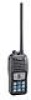
3 PANEL DESCRIPTION ■ Front, top, side and rear panels 1 q ANTENNA CONNECTOR (p. 2) q Connects to the supplied antenna. 2 w w SPEAKER-MICROPHONE CONNECTOR [SP MIC] (p. 94) 3 Connects to the optional external speaker-microphone. 4 NOTE: Attach the [SP MIC] cap when the optional speaker-microphone is not used. Otherwise, water will 5 Function get into the transceiver. 6 e display (pp. 7, 8, 9) e PTT SWITCH [PTT] Hold down to transmit; release to receive. (p. 14) 7 !2 r MENU KEY 8 r !1 Push to enter or exit the Menu screen. !0 t LEFT AND RIGHT KEYS [Ω]/[≈] 9 t o ➥ Push to switch to the previous or next key function that 10 y i is assigned to the softkeys. (p. 9) 11 ➥ Push to select the desired character or number in the u table while in the channel name, position, MMSI code 12 Speaker programming mode, and so on. (pp. 10, 16, 23) 13 /+% Microphone y VOLUME/SQUELCH KEY [VOL/SQL] ➥ Push to enter the volume level adjustment mode. 14 (p. 13) 15 ➥ Push again while in the volume level adjustment mode to enter the squelch level adjustment mode. 16 ➥ Hold down for 1 second to activate the monitor function. (p. 15) Distress key (p. 24) u POWER KEY [ ] Hold down for 1 second to turn the power ON or OFF. 4
-
 1
1 -
2
-
3
-
4
-
5
-
 6
6 -
 7
7 -
 8
8 -
 9
9 -
 10
10 -
 11
11 -
 12
12 -
 13
13 -
 14
14 -
 15
15 -
 16
16 -
17
-
18
-
19
-
20
-
21
-
22
-
23
-
24
-
25
-
26
-
27
-
28
-
29
-
30
-
31
-
32
-
33
-
34
-
35
-
36
-
37
-
38
-
39
-
40
-
41
-
42
-
43
-
44
-
45
-
46
-
47
-
48
-
49
-
50
-
51
-
52
-
53
-
54
-
55
-
56
-
57
-
58
-
59
-
60
-
61
-
62
-
63
-
64
-
65
-
66
-
67
-
68
-
69
-
70
-
71
-
72
-
73
-
74
-
75
-
76
-
77
-
78
-
79
-
80
-
81
-
82
-
83
-
84
-
85
-
86
-
87
-
88
-
89
-
90
-
91
-
92
-
93
-
94
-
95
-
96
-
97
-
98
-
99
-
100
-
101
-
102
-
103
-
104
-
105
-
106
-
107
-
108
 |
 |
