Intel S875WP1 Product Guide
Intel S875WP1 - EATX MBD 875 P4 DDR-2CH SATA RAID VID GETH Manual
 |
UPC - 735858161381
View all Intel S875WP1 manuals
Add to My Manuals
Save this manual to your list of manuals |
Intel S875WP1 manual content summary:
- Intel S875WP1 | Product Guide - Page 1
Intel® Server Board S875WP1-E Product Guide A Guide for Technically Qualified Assemblers of Intel® Identified Subassemblies/Products Order Number: C32693-002 - Intel S875WP1 | Product Guide - Page 2
instructions. See also Intel Server Boards and Server Chassis Safety Information on the Resource CD and/or at http:\\support.intel.com. Disclaimer Intel Corporation (Intel purpose. Intel assumes no responsibility for any errors that may appear in this document. Intel makes no commitment to update nor - Intel S875WP1 | Product Guide - Page 3
9 Server Board Connector and Component Locations 11 Back Panel Connectors 12 Front Panel Connectors 12 Processor ...13 Memory ...13 Intel 875P Chipset...14 Intel 82875P Memory Controller Hub (MCH 14 Intel 82801EB I/O Controller Hub (ICH5-R 15 Intel 82802AC Firmware Hub (FWH 15 Video ...15 - Intel S875WP1 | Product Guide - Page 4
Panel Header 55 Connecting the USB 2.0 Header 56 Connecting Hardware Control and Power Cables 57 Connecting Fans ...58 Chassis Intrusion...58 Connecting Power Cables 58 Setting the BIOS Configuration Jumper 58 Clearing Passwords ...59 Replacing the Battery...60 iv Intel Server Board S875WP1 - Intel S875WP1 | Product Guide - Page 5
92 ATAPI CDROM Drives Submenu 92 Exit Menu ...93 4 Solving BIOS Problems 95 BIOS Beep Codes...95 BIOS Error Messages ...96 5 Getting Help 99 World Wide Web ...99 Telephone ...99 6 Technical Reference 101 Server Board Connectors...101 Baseboard Connectors 102 Power, Fan, Chassis Intrusion - Intel S875WP1 | Product Guide - Page 6
Server Board Resources...104 Memory Map ...104 DMA Channels ...104 I/O Map ...105 Installation Precautions ...111 Installation Requirements...111 Prevent Power Supply Overload 111 Place Battery Marking 112 Use Only for Intended Applications 112 vi Intel Server Board S875WP1-E Product Guide - Intel S875WP1 | Product Guide - Page 7
Gigabit Ethernet LAN Connector LEDs 24 Effects of Pressing the Power Switch under ACPI 25 Wake-up Devices and Events 26 Fan Connector Function/Operation 28 Supervisor and User Password Functions 31 Front Panel Header (J7J1 55 USB 2.0 Header (J7E1 56 Jumper Settings for the BIOS Setup Program - Intel S875WP1 | Product Guide - Page 8
Video Configuration Submenu 81 USB Configuration Submenu 82 Chipset Configuration Submenu 83 Fan Control BIOS Error Messages 96 System Memory Map 104 DMA Channels 104 I/O Map...105 Interrupts ...106 Product Certification Markings 108 viii Intel Server Board S875WP1-E Product Guide - Intel S875WP1 | Product Guide - Page 9
(S875WP1) with support for RAID 0 and 1 planned or six Serial ATA connectors (S875WP1LX) with support for RAID 0, 1, and 10 • One floppy drive interface with support for one drive • PS/2* keyboard and mouse ports LAN • One Intel® 82562ET 10/100 Fast Ethernet Controller • One Intel® 82547EI - Intel S875WP1 | Product Guide - Page 10
Interface (ACPI) • 8 megabit symmetrical flash memory • Support for SMBIOS • Intel® Rapid BIOS Boot • Intel® Express BIOS Update Power Management Support for ACPI: • Suspend to RAM (STR) • Wake on USB, PCI, RS-232, PS/2, LAN, and front panel Hardware Management Hardware monitor with: • Four - Intel S875WP1 | Product Guide - Page 11
Header W. Front Panel USB Header X. Clear CMOS Jumper J8G1 Y. SATA-B1 and SATA-B2 Connectors (slots numbered from left to right) Z. AGP Connector AA. NIC2 (10/100 Mb) BB. NIC1 (1 Gb) CC. Back Panel I/O Ports Q. Hot Swap Backplane Header Figure 1. Server Board Components Server Board Features 11 - Intel S875WP1 | Product Guide - Page 12
port H. USB ports 1 and 2 D. Serial port A I. USB ports 3 and 4 E. Video port Figure 2. Back Panel Connectors Front Panel Connectors Figure 3 shows the location of the front panel connectors. TP00183 A B A. SCSI LED Header B. Front Panel Header Figure 3. Front Panel Connectors TP00184 12 - Intel S875WP1 | Product Guide - Page 13
512 KB 512 KB ✏ NOTE The processor is not included with the server board and must be purchased separately. Memory The S875WP1-E server board contains four 184-pin DIMM sockets and supports up to four DDR SDRAM DIMMs. The minimum supported memory configuration is 128 MB and the maximum configurable - Intel S875WP1 | Product Guide - Page 14
default. The MCH controls the Intel 82547EI from the CSA interface. The MCH provides the following: • An integrated DDR memory controller with auto detection. • Support for ACPI Rev 2.0 compliant power management. • AGP 2.0 slot, also known as AGP 8x 14 Intel Server Board S875WP1-E Product Guide - Intel S875WP1 | Product Guide - Page 15
System BIOS program • Logic that enables protection for storing and updating of platform information Video The server board S875WP1-E contains two separate, mutually exclusive graphics subsystems. You can use either the AGP connector or the ATI Rage XL video controller. When an AGP card is installed - Intel S875WP1 | Product Guide - Page 16
bpp modes under 3D. It also supports both CRT and LCD monitors up to 100 Hz vertical refresh rate. The server board S875WP1-E provides a standard 15-pin VGA connector and supports disabling of the on-board video through the BIOS Setup menu or when a plug-in video card is installed in the AGP slot or - Intel S875WP1 | Product Guide - Page 17
coprocessor, the display controller, the video scalar, and hardware cursor. Requests are serviced in a manner that ensures display integrity and maximum CPU/coprocessor drawing performance. The server board S875WP1-E supports an 8 MB (512Kx32bitx4 Banks) SDRAM device for video memory. Super I/O The - Intel S875WP1 | Product Guide - Page 18
. The keyboard controller contains the AMI keyboard and mouse controller code, provides the keyboard and mouse control functions, and supports password protection for power-on/reset. A power-on/reset password can be specified in the BIOS Setup program. 18 Intel Server Board S875WP1-E Product Guide - Intel S875WP1 | Product Guide - Page 19
BIOS Setup program, and to install an operating system that supports USB. By default, Legacy USB support is set to Enabled. Four of the USB ports are implemented with stacked back panel connectors; the other two are accessible via the front panel USB header. The S875WP1-E server board fully supports - Intel S875WP1 | Product Guide - Page 20
devices are not supported in legacy mode. PCI I/O Subsystem The primary I/O bus for the server board S875WP1-E is PCI, with one independent PCI bus. The PCI bus complies with the PCI Local Bus Specification, Rev 2.3. The PCI bus is directed through the Intel 82801EB I/O Controller Hub (ICH5-R). The - Intel S875WP1 | Product Guide - Page 21
limited to a maximum of 133 MB/sec. For instructions on installing and configuring Serial ATA RAID on the 4-port Promise Controller that is available on the server board S875WP1LX, please see http://support.intel.com/support/motherboards/server/s875wp1e/sata-install.htm Server Board Features 21 - Intel S875WP1 | Product Guide - Page 22
drive reports the transfer rate and translation mode to the BIOS. The S875WP1-E server board supports Laser Servo (LS-120) diskette technology through the IDE interfaces. An LS-120 drive can be configured as a boot device by setting the BIOS Setup program's Boot menu to one of the following: • ARMD - Intel S875WP1 | Product Guide - Page 23
Network Interface Controller (NIC) The server board S875WP1-E supports two Network Interface Controllers (NICs), one that runs at 10/100Mb and is based on the Intel 82562ET NIC and the other that runs at one gigabit and is based on the Intel 82547EI NIC. When looking at the rear of the chassis, the - Intel S875WP1 | Product Guide - Page 24
board is powered up and the 82547EI 10/100/1000 Gigabit Ethernet LAN subsystem is operating. Table 7. 10/100/1000 Gigabit Ethernet LAN Connector LEDs LED Color LED State Indicates Green (left LED) Off On (steady state) LAN link is not established. LAN Intel Server Board S875WP1-E Product Guide - Intel S875WP1 | Product Guide - Page 25
events • Support for a front panel power and sleep mode switch The Server Board S875WP1-E supports sleep states S0, S1, S2, S3, S4, and S5. When the server board is operating in ACPI mode, the operating system retains control of the system and the operating system policy determines the entry methods - Intel S875WP1 | Product Guide - Page 26
PCI bus PME# signal for PCI 2.2 compliant LAN designs • The onboard LAN subsystem PCI via PME# Wake-up Support When the PME# signal on the PCI bus is asserted, the computer wakes from an ACPI S1, S3, S4, or S5 state (with Wake on PME enabled in BIOS). 26 Intel Server Board S875WP1-E Product Guide - Intel S875WP1 | Product Guide - Page 27
rear or the chassis or to an internally installed modem. Resume on ring can be summarized Support The S875WP1-E server board provides several power management hardware features, including: • Power connector • Fan connectors • Instantly Available PC technology Instantly Available PC technology and LAN - Intel S875WP1 | Product Guide - Page 28
with an ATX12V or EPS12V compliant power supply that supports remote power on/off, the S875WP1-E server board can turn off the system power through software control. When the system BIOS receives the correct command from the operating system, the BIOS turns off power to the computer. With soft-off - Intel S875WP1 | Product Guide - Page 29
current when implementing Instantly Available PC technology can damage the power supply. The S875WP1-E server board supports the PCI Bus Power Management Interface Specification. An add-in board that supports this specification can participate in power management and can be used to wake the computer - Intel S875WP1 | Product Guide - Page 30
and user guides that provide more information on using Intel LDCM software are available on the Intel Server Board S875WP1-E Resource CD and are also available for download at: http://www.support.intel.com/support/motherboards/server/S875WP1-E Chassis Intrusion and Detection The server board S875WP1 - Intel S875WP1 | Product Guide - Page 31
change a Supervisor Password options limited number Enter Password of options Note: If no password is set, any user can change all Setup options. Password to Enter Setup None Supervisor User Supervisor or user Password During Boot None None User Supervisor or user Server Board Features 31 - Intel S875WP1 | Product Guide - Page 32
all AC power cables. 2. Remove the cover from the chassis. 3. Move the jumper at jumper block J8G1 to cover pins 2 and three. For the location of jumper block J8G1, see the figure below. J8G1 12 3 Figure 5. Location of Clear CMOS Jumper TP00200 32 Intel Server Board S875WP1-E Product Guide - Intel S875WP1 | Product Guide - Page 33
can be updated using a disk-based program. The FWH contains the BIOS Setup program, POST, the PCI auto-configuration utility, and Plug and Play support. The S875WP1-E server board supports system BIOS shadowing, allowing the BIOS to execute from 64-bit onboard write-protected system memory. The BIOS - Intel S875WP1 | Product Guide - Page 34
are supported in two languages: US English and Spanish. Additional languages may be flashed in if desired (German, Italian, and French available). The default language of US English is used unless another language is selected in the BIOS Setup program. 34 Intel Server Board S875WP1-E Product Guide - Intel S875WP1 | Product Guide - Page 35
created and the BIOS update files copied to it. BIOS upgrades and the Intel Flash Memory Update Utility are available from Intel Customer Support through the Intel World Wide Web booting from the on-board NIC or a network add-in card with a remote boot ROM installed. Server Board Features 35 - Intel S875WP1 | Product Guide - Page 36
save several seconds of painting complex graphic images and changing video modes. • Enabled Intel® Rapid BIOS Boot. This feature bypasses memory count and the search for a diskette drive. ✏ in the Drive Configuration Submenu of the BIOS Setup program). 36 Intel Server Board S875WP1-E Product Guide - Intel S875WP1 | Product Guide - Page 37
capabilities, operational status, and installation dates for system components. BIOS supports an SMBIOS table interface for such operating systems. Using this support, an SMBIOS service-level application running on a non-Plug and Play operating system can obtain the SMBIOS information. Server Board - Intel S875WP1 | Product Guide - Page 38
- Intel S875WP1 | Product Guide - Page 39
more information please contact your local Intel Representative. See "Regulatory and server and disconnect the power cord, telecommunications systems, networks, and modems attached to the server before opening it. Otherwise, personal injury or equipment damage can result. Server Board Installation - Intel S875WP1 | Product Guide - Page 40
pliers to remove or install a jumper; grip the problems with the function controlled by that jumper. Take care to grip, but not squeeze, with the pliers or other tool you use to remove a jumper, or you may bend or break the stake pins on the board. 40 Intel Server Board S875WP1-E Product Guide - Intel S875WP1 | Product Guide - Page 41
Shield CAUTION Systems based on the S875WP1-E server board need the I/O shield properly installed to pass emissions (EMI) certification testing and to meet Class A emissions compliance levels. Without the I/O shield, or with an improperly installed I/O shield, the server system will not meet Class - Intel S875WP1 | Product Guide - Page 42
1, 4, 6, 20, 23, and 26. Install standoffs in the bottom of the chassis at positions 7, 10, 13, 17, 18, and 19. Standoffs are included with your chassis. 1 7 17 4 10 18 6 13 19 TP00187 Figure 7. Installing Chassis Standoffs in the SC5200 Chassis 42 Intel Server Board S875WP1-E Product Guide - Intel S875WP1 | Product Guide - Page 43
pre-installed in positions K, E, A, N, I, and D. Install standoffs in the bottom of the chassis at positions L, 3, 1, M, H, and C. Standoffs are included with your chassis. K LM E 3 H A 1C TP00188 Figure 8. Installing Chassis Standoffs in the SC5250-E Chassis Server Board Installation and - Intel S875WP1 | Product Guide - Page 44
personnel should attempt this procedure. Disconnect the server from its power source before performing the procedures described here. Failure to disconnect the power before you open the server can result in personal injury or equipment damage. 44 Intel Server Board S875WP1-E Product Guide - Intel S875WP1 | Product Guide - Page 45
to the chassis at the 9 locations shown in Figure 10. SC5200 SC5250-E Figure 10. Attaching the Server Board TP00189 Installing the Processor To install a processor, follow these instructions: 1. Observe the safety and ESD precautions at the beginning of this chapter. 2. Locate the processor - Intel S875WP1 | Product Guide - Page 46
top of the processor. 6. Place the fan heat sink on top of the processor. TP00208 Figure 12. Attaching the Heat Sink to the Processor 46 Intel Server Board S875WP1-E Product Guide - Intel S875WP1 | Product Guide - Page 47
be necessary to exert pressure to close the levers. See Figure 14. TP00206 Figure 14. Attaching the Fan Heat Sink Clips to the Processor Socket Server Board Installation and Upgrades 47 - Intel S875WP1 | Product Guide - Page 48
Cable to the Processor Fan Connector Removing the Processor To remove the processor, follow these instructions: 1. Observe the safety and ESD precautions at the beginning of this chapter. 2. . 6. Lift the processor lever. 7. Remove the processor. 48 Intel Server Board S875WP1-E Product Guide - Intel S875WP1 | Product Guide - Page 49
the Intel Customer Support website for the latest tested memory list: http://support.intel.com/support/motherboards/server/S875WP1-E DIMM Installation Guidelines All memory components and DIMMs used with the server board S875WP1-E must comply with the DDR specifications. Server Board Installation - Intel S875WP1 | Product Guide - Page 50
down on the top edge of the DIMM until the retaining clips snap into place. Make sure the clips are firmly in place. 9. Replace the server's cover and reconnect the AC power cord. 50 Intel Server Board S875WP1-E Product Guide - Intel S875WP1 | Product Guide - Page 51
not attempt to install a legacy 3.3 V AGP card. The AGP connector is not mechanically compatible with legacy 3.3 V AGP cards. The AGP connector supports 1.5 V 8X, 4X, and 2X AGP cards. The server board has an integrated AGP card retention mechanism (RM). Server Board Installation and Upgrades 51 - Intel S875WP1 | Product Guide - Page 52
the card's metal bracket to the chassis back panel. 3. Pull back on the retention mechanism lever (marked "A" in the figure above to release the retention pin from the notch in the card. 4. Pull straight up on the card to pull it from the socket. 52 Intel Server Board S875WP1-E Product Guide - Intel S875WP1 | Product Guide - Page 53
Cable The Intel® boxed server board package includes a 40-contact, 80-conductor IDE cable. This cable is capable of connecting two drives to the server board. The cable supports Ultra ATA/ connector (P3). A TP00192 B Figure 18. Connecting the IDE Cable Server Board Installation and Upgrades 53 - Intel S875WP1 | Product Guide - Page 54
TP00193 ✏ NOTE For instructions on installing and configuring Serial ATA RAID on the 4-port Promise Controller that is available on the server board S875WP1LX, please see http://support.intel.com/support/motherboards/server/s875wp1e/sata-install.htm 54 Intel Server Board S875WP1-E Product Guide - Intel S875WP1 | Product Guide - Page 55
39. Figure 20 (above) shows the location of the front panel header. Table 12 shows the pin assignments for the front panel header. Table 12. Front Panel Header (J7J1) Pin Signal Name Pin(s) 1 Power LED Activity LED Cathode I1C SDA I2C SDA continued Server Board Installation and Upgrades 55 - Intel S875WP1 | Product Guide - Page 56
the location of the USB 2.0 header. Table 13 shows the pin assignments for the front panel header. Table 13. USB 2.0 Header (J7E1) Pin Signal name 1 USB_FNT1_PWR 3 USB_FNT1_PWR 4 USB_FRONT2_L* 6 USB_FRONT2_L 8 Ground 10 USB_ OC_FNT_R1 56 Intel Server Board S875WP1-E Product Guide - Intel S875WP1 | Product Guide - Page 57
control (fans and chassis intrusion) headers and power supply connectors. J1B1 A B J1F1 C 12 V I J7B1 H D E J6J3 F J6J2 G A. System Fan 4 Header B. CPU I. +12V CPU Power Connector Figure 21. Location of the Fan Headers and Power Connectors Server Board Installation and Upgrades 57 - Intel S875WP1 | Product Guide - Page 58
Always turn off the power and unplug the power cord from the server before changing the jumper. Moving the jumper with the power on may result in unreliable server operation. J8J2 3 2 1 Figure 22. BIOS Configuration Jumper Block Location TP00196 58 Intel Server Board S875WP1-E Product Guide - Intel S875WP1 | Product Guide - Page 59
This three-pin jumper block, shown in Figure 22, enables all server board configurations to be done in BIOS Setup. Table 14 shows the jumper settings for the Setup program modes. Table 14. Jumper Settings for the BIOS Setup Program Modes (J8J2) Jumper Setting 13 13 Mode Normal (default) (1-2) - Intel S875WP1 | Product Guide - Page 60
RAM. The location of the server board battery is shown in Figure 23 on page 62. The battery should last about seven years whereupon it begins to lose voltage. When the voltage drops below a certain level, the BIOS Setup program settings stored in CMOS RAM Intel Server Board S875WP1-E Product Guide - Intel S875WP1 | Product Guide - Page 61
baterias devem ser recicladas nos locais apropriados. A eliminação de baterias usadas deve ser feita de acordo com as regulamentações ambientais da região. (Brazilian Portuguese) Server Board Installation and Upgrades 61 - Intel S875WP1 | Product Guide - Page 62
tab away from the battery. Pull out the battery. Note the orientation of the "+"on the battery. 6. Install the new battery in the connector, orienting the "+" as shown in Figure 23. 7. Replace the server cover. Figure 23. Removing the Battery TP00197 62 Intel Server Board S875WP1-E Product Guide - Intel S875WP1 | Product Guide - Page 63
BIOS. The BIOS update file contains: • New BIOS files • BIOS recovery files • Intel Flash Memory Update Utility You can obtain the BIOS update file through your server supplier or from the Intel World Wide Web site: http://support.intel.com/support/motherboards/server/ ✏ NOTE Review the instructions - Intel S875WP1 | Product Guide - Page 64
. 4. To extract the files, double click on the BIOS update file, for example, EABIOSxx.EXE. 5. One of the extracted files is MK_BOOTZ.EXE. Double click on this file to extract the README.TXT file. 6. Follow the directions in the README.TXT file. 64 Intel Server Board S875WP1-E Product Guide - Intel S875WP1 | Product Guide - Page 65
Creating a BIOS Update Media 1. Obtain the BIOS update file through your server supplier or from the Intel World Wide Web site: http://support.intel.com/support/motherboards/server/ 2. Copy the BIOS update file to a temporary directory on your hard disk. 3. From the C:\ prompt, change to the - Intel S875WP1 | Product Guide - Page 66
press . 6. To accept the defaults, press . 7. In Setup, enter the settings you wrote down before beginning the BIOS upgrade. 8. To save the settings, press . 9. To accept the settings, press . 10. Turn off the server and reboot. 66 Intel Server Board S875WP1-E Product Guide - Intel S875WP1 | Product Guide - Page 67
Remove the jumper from all pins as shown below to set recovery mode for Setup. 3 1 4. Insert the bootable BIOS update diskette into diskette drive A. 5. Replace the server cover, connect the power cord, turn on the server, and allow it to boot. The recovery process will take a few minutes. Listen - Intel S875WP1 | Product Guide - Page 68
power management features Selects boot options and power supply controls Saves or discards changes to Setup program options * For information about the BIS, refer to the Intel Web site at: http://developer.intel.com/design/security/index1.htm 68 Intel Server Board S875WP1-E Product Guide - Intel S875WP1 | Product Guide - Page 69
menu. Save the current values and exits the BIOS Setup program. Exits the menu. Maintenance Menu This menu Service (BIS) credentials. CPU Stepping Signature No options Displays CPU's Stepping Signature. CPU Microcode Update Revision No options Displays CPU's Microcode Update - Intel S875WP1 | Product Guide - Page 70
• Day of week Month/day/year Set current date. Use the Tab key to navigate fields. ✏ NOTE Additional language support is available. For more information visit Intel's support web site at: www.support.intel.com/support/motherboards/server/S875WP1-E 70 Intel Server Board S875WP1-E Product Guide - Intel S875WP1 | Product Guide - Page 71
PCI Configuration Boot Configuration Peripheral Configuration Drive Configuration Floppy Configuration Event Log Configuration Video Configuration USB Configuration Chipset Configuration Fan Control Configuration Hardware Monitoring Remote Access Configuration Boot Exit Table 19 describes the - Intel S875WP1 | Product Guide - Page 72
Configuration Video Configuration USB Configuration Chipset Configuration Fan Control Configuration 5 • 9 • 10 • 11 Notes: 1. Additional interrupts may be available if certain on-board devices (such as the serial and parallel ports) are disabled. 72 Intel Server Board S875WP1-E Product Guide - Intel S875WP1 | Product Guide - Page 73
Log Configuration Video Configuration USB Configuration Chipset Configuration Fan Control Configuration Hardware Monitoring Plug and Play O/S • No (default) • Yes Specifies if manual configuration is desired. No lets the BIOS configure all devices. This setting is appropriate when using a Plug - Intel S875WP1 | Product Guide - Page 74
Video Configuration USB Configuration Chipset Configuration Fan Control Configuration Hardware Monitoring Remote Access Configuration The submenu represented in Table 22 is used for configuring server the interrupt for serial port B. continued 74 Intel Server Board S875WP1-E Product Guide - Intel S875WP1 | Product Guide - Page 75
or disables the on-board LAN#2 device. • Enabled (default) ATI Rage XL Video • Disabled • Enabled (default) Enables or disables the on-board ATI* Rage XL video controller. Promise PDC20319 S150 TX4 • Disabled • Enabled (default) Enables or disables RAID support. Configuration Software and - Intel S875WP1 | Product Guide - Page 76
Video Configuration USB Configuration Chipset Configuration Fan Control IDE controller. When Legacy is selected, a maximum of 4 drives can be installed. When Enhanced is selected, a maximum of 6 drives can be installed. Legacy Disabled continued 76 Intel Server Board S875WP1-E Product Guide - Intel S875WP1 | Product Guide - Page 77
Specifies the hard disk drive pre-delay. • 3 Seconds • 6 Seconds • 9 Seconds • 12 Seconds • 15 Seconds • 21 Seconds • 30 Seconds Intel (R) RAID Technology • Disabled (default) • Enabled SATA Port -0 Select to display submenu Reports type of connected SATA device. When selected, displays - Intel S875WP1 | Product Guide - Page 78
Video Configuration USB Configuration Chipset Configuration Fan Control Master/Slave Submenus Feature Options Description Drive Installed No options Displays the type of drive installed. Type • User • Auto (default = Ultra DMA continued 78 Intel Server Board S875WP1-E Product Guide - Intel S875WP1 | Product Guide - Page 79
66/100 devices). Note: These configuration options appear only if an IDE device is installed. Floppy Configuration Submenu To access this menu, select Advanced on the menu bar, Log Configuration Video Configuration USB Configuration Chipset Configuration Fan Control Configuration Hardware - Intel S875WP1 | Product Guide - Page 80
Floppy Configuration Event Log Configuration Video Configuration USB Configuration Chipset Configuration Fan Control Configuration Hardware Monitoring Remote Access (default) Mark Events As Read • OK (default) Marks all events as read. • Cancel 80 Intel Server Board S875WP1-E Product Guide - Intel S875WP1 | Product Guide - Page 81
Aperture Size • 4MB • 8MB • 16MB • 32MB • 64MB (default) • 128MB • 256MB Primary Video Adapter • AGP (default) • PCI Description Sets the aperture size for the AGP video controller. Allows selecting an AGP or PCI video controller as the display device that will be active when the system - Intel S875WP1 | Product Guide - Page 82
Log Configuration Video Configuration USB Configuration Chipset Configuration Fan Control Configuration Hardware driver. Disable this option if the driver is not available. Allows the use of legacy USB accessories. FullSpeed = 480 Mbps HiSpeed = 12 Mbps 82 Intel Server Board S875WP1-E Product Guide - Intel S875WP1 | Product Guide - Page 83
PCI Configuration Boot Configuration Peripheral Configuration Drive Configuration Floppy Configuration Event Log Configuration Video Configuration USB Configuration Chipset Configuration Fan Control Configuration Hardware Monitoring Remote Access Configuration Boot Exit The submenu represented by - Intel S875WP1 | Product Guide - Page 84
. When enabled, it allows the DRAM controller to attempt chip select assertions in two consecutive common clocks. SDRAM RAS Act. To Pre. No options SDRAM CAS# Latency No options SDRAM RAS# to CAS delay No options SDRAM RAS# Precharge No options 84 Intel Server Board S875WP1-E Product Guide - Intel S875WP1 | Product Guide - Page 85
PCI Configuration Boot Configuration Peripheral Configuration Drive Configuration Floppy Configuration Event Log Configuration Video Configuration USB Configuration Chipset Configuration Fan Control Configuration Hardware Monitoring Remote Access Configuration Boot Exit The submenu represented by - Intel S875WP1 | Product Guide - Page 86
Log Configuration Video Configuration USB Configuration Chipset Configuration Fan Control Configuration Hardware for the front fan. Displays voltage level. Displays voltage level. Displays voltage level. Displays voltage level. Displays voltage level. 86 Intel Server Board S875WP1-E Product Guide - Intel S875WP1 | Product Guide - Page 87
Log Configuration Video Configuration USB Configuration Chipset Configuration Fan Control Configuration Hardware the serial port to use for console redirection. In addition to selecting the port number in BIOS setup, make sure the selected port is enabled for use. Serial Port Mode • 115200 8,n,1 - Intel S875WP1 | Product Guide - Page 88
. Clears the user password. Sets BIOS Setup Utility access rights for user level. No Access: User cannot access BIOS Setup. View Only: User can view BIOS Setup, but cannot make any changes. both a user password and a supervisor password have been set. 88 Intel Server Board S875WP1-E Product Guide - Intel S875WP1 | Product Guide - Page 89
submenu. Specifies the mode of operation if an AC power loss occurs. Power On restores power to the server. Stay Off keeps the power off until Feature Options ACPI Suspend State • S1 State • S3 State (default) Wake on LAN from S5 • Stay Off (default) • Power On Description Specifies the ACPI - Intel S875WP1 | Product Guide - Page 90
Enabled AddOn ROM Display Mode Intel® Rapid BIOS Boot Scan User Flash Area PXE Boot to LAN USB Boot Boot Device Priority Removable boot without running certain POST tests. Enables the BIOS to scan the flash memory for user binary files that are executed at Intel Server Board S875WP1-E Product Guide - Intel S875WP1 | Product Guide - Page 91
1) Options • Removable Dev. • Hard Drive • ATAPI CD-ROM • Intel® UNDI, PXE • Disabled Description Specifies the boot sequence from the available types is installed. This list will display up to twelve hard disk drives, the maximum number of hard disk drives supported by the BIOS. Configuration - Intel S875WP1 | Product Guide - Page 92
as the intended boot device. Note: This boot device submenu appears only if at least one boot device of this type is installed. This list will display up to four ATAPI CDROM drives, the maximum number of ATAPI CDROM drives supported by the BIOS. 92 Intel Server Board S875WP1-E Product Guide - Intel S875WP1 | Product Guide - Page 93
, the BIOS reads the Setup values from flash memory. If this memory is corrupted, the BIOS reads the custom defaults. If no custom defaults are set, the BIOS reads the factory defaults. Discard Changes Discards changes without exiting Setup. The option values present when the server was turned - Intel S875WP1 | Product Guide - Page 94
- Intel S875WP1 | Product Guide - Page 95
BIOS Problems The board reports POST errors in two ways: • By sounding a beep code • By displaying an error message on the monitor BIOS Beep Codes The BIOS beep codes are listed in Table 42. The BIOS also issues a beep code (one long tone followed by two short tones) during POST if the video - Intel S875WP1 | Product Guide - Page 96
invalid and has been updated. Updated Failed NVRAM was invalid but was unable to be updated. Keyboard Error Error in the keyboard connection. Make sure keyboard is connected properly. KB/Interface Error Keyboard interface test failed. continued 96 Intel Server Board S875WP1-E Product Guide - Intel S875WP1 | Product Guide - Page 97
in onboard memory at an unknown address. NVRAM / CMOS / PASSWORD cleared by Jumper NVRAM, CMOS, and passwords have been cleared. The system should be powered down and the jumper removed. Pressed CMOS is ignored and NVRAM is cleared. User must enter Setup. Solving BIOS Problems 97 - Intel S875WP1 | Product Guide - Page 98
- Intel S875WP1 | Product Guide - Page 99
5 Getting Help World Wide Web http://support.intel.com/support/motherboards/server/S875WP1-E Telephone All calls are billed US $25.00 per incident, levied in local currency at the applicable credit card exchange rate plus applicable taxes. (Intel reserves the right to change the pricing for - Intel S875WP1 | Product Guide - Page 100
- Intel S875WP1 | Product Guide - Page 101
Server Board Connectors CAUTION Many of the baseboard and front panel connectors provide operating voltage (+5 V DC and +12 V DC, for example) to devices inside the server to power the server board S875WP1-E. Plug the power cables into the pin 1 end of their respective motherboard connectors, leaving - Intel S875WP1 | Product Guide - Page 102
A. Chassis fan E. Chassis fan B. Processor fan F. Chassis fan C. Main power G. Chassis intrusion D. Auxiliary power H. +12V power Figure 24. Power, Fan, and Chassis Intrusion Connectors 102 Intel Server Board S875WP1-E Product Guide - Intel S875WP1 | Product Guide - Page 103
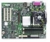
Interface Connectors Figure 25 shows the add-in board and peripheral interface connectors. L K A T A 1 0 J0 A B C D E F GH I Serial ATA A. PCI slot 1 B. PCI slot 2 C. PCI slot 3 D. Serial ATA Drive SATA-A4 (S875WP1LX only) E. Serial ATA Drive SATA-A2 (S875WP1LX only) F. Serial ATA Drive SATA-A3 - Intel S875WP1 | Product Guide - Page 104
memory Runtime BIOS Reserved Available high DOS memory (open to the PCI bus) Video memory and BIOS Extended BIOS data (movable by memory manager software) Extended conventional memory Conventional memory (for ECP or EPP) DMA controller Open Open Open 104 Intel Server Board S875WP1-E Product Guide - Intel S875WP1 | Product Guide - Page 105
01F0 - 01F7 256 bytes 8 bytes 8 bytes Used by the Server Board S875WP1-E. Refer to the ICH5-R data sheet for dynamic addressing information. bytes LPT3 LPT2 COM4/video (8514A) COM2 Secondary IDE channel command port Secondary IDE channel status port LPT1 Intel 82875P MCH Intel 82875P MCH COM3 - Intel S875WP1 | Product Guide - Page 106
2 (through PIRQD) 20 ICH5-R LAN (through PIRQE) 21 User available (through PIRQF) 22 User available (through PIRQG) 23 ICH5-R USB 2.0 EHCI controller/User available (through PIRQH) Note: 1. Default, but can be changed to another IRQ. 106 Intel Server Board S875WP1-E Product Guide - Intel S875WP1 | Product Guide - Page 107
Safety Compliance The server board S875WP1-E complies with the following safety requirements: • UL 1950 - CSA 950 (US/Canada) • server board S875WP1-E has been has been tested and verified to comply with the following electromagnetic compatibility (EMC) regulations when installed a compatible Intel - Intel S875WP1 | Product Guide - Page 108
48. Product Certification Markings UL Recognition Mark CE Mark Russian GOST Mark Australian C-Tick Mark BSMI DOC Marking BSMI EMC Warning RRL MIC Mark 108 Intel Server Board S875WP1-E Product Guide - Intel S875WP1 | Product Guide - Page 109
questions related to the EMC performance of this product, contact: Intel Corporation 5200 N.E. Elam Young Parkway Hillsboro, OR 97124 1-800 interference will not occur in a particular installation. If this equipment does cause harmful interference to radio or television reception, which can be - Intel S875WP1 | Product Guide - Page 110
radioé Intel 4. Date of Manufacturer: Marked on Product 5. Manufacturer / Nation : Intel Australia / New Zealand This product has been tested and complies with AS/NZS 3548. The product has been marked with the C-Tick mark to illustrate compliance. 110 Intel Server Board S875WP1-E Product Guide - Intel S875WP1 | Product Guide - Page 111
Precautions When you install and test the server board, observe all warnings and cautions in the installation instructions. To avoid injury, be careful of: • Sharp pins on connectors • Sharp pins on printed circuit assemblies • Rough edges and sharp corners on the chassis • Hot - Intel S875WP1 | Product Guide - Page 112
be installed in offices, homes, schools, computer rooms, and similar locations. The suitability of this product for other applications or environments, (such as medical, industrial, alarm systems, test equipment, etc.) may require further evaluation. 112 Intel Server Board S875WP1-E Product Guide
-
 1
1 -
 2
2 -
 3
3 -
 4
4 -
 5
5 -
 6
6 -
 7
7 -
8
-
9
-
10
-
11
-
12
-
13
-
14
-
15
-
16
-
17
-
18
-
19
-
20
-
21
-
22
-
23
-
24
-
25
-
26
-
27
-
28
-
29
-
30
-
31
-
32
-
33
-
34
-
35
-
36
-
37
-
38
-
39
-
40
-
41
-
42
-
43
-
44
-
45
-
46
-
47
-
48
-
49
-
50
-
51
-
52
-
53
-
54
-
55
-
56
-
57
-
58
-
59
-
60
-
61
-
62
-
63
-
64
-
65
-
66
-
67
-
68
-
69
-
70
-
71
-
72
-
73
-
74
-
75
-
76
-
77
-
78
-
79
-
80
-
81
-
82
-
83
-
84
-
85
-
86
-
87
-
88
-
89
-
90
-
91
-
92
-
93
-
94
-
95
-
96
-
97
-
98
-
99
-
100
-
101
-
102
-
103
-
104
-
105
-
106
-
107
-
108
-
109
-
110
-
111
-
112
 |
 |

Intel
®
Server Board S875WP1-E
Product Guide
A Guide for Technically Qualified Assemblers of Intel
®
Identified
Subassemblies/Products
Order Number:
C32693-002