Intel S875WP1 Product Guide - Page 55
Connecting Internal Headers, Connecting the Front Panel Header
 |
UPC - 735858161381
View all Intel S875WP1 manuals
Add to My Manuals
Save this manual to your list of manuals |
Page 55 highlights
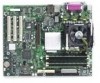
Connecting Internal Headers Before connecting internal headers, observe the precautions in "Before You Begin" on page 39. B 1 2 A2 10 1 9 A Front Panel USB 2.0 Header B Front Panel Header Figure 20. Location of Internal Headers 33 34 TP00194 Connecting the Front Panel Header Before connecting the front panel header, observe the precautions in "Before You Begin" on page 39. Figure 20 (above) shows the location of the front panel header. Table 12 shows the pin assignments for the front panel header. Table 12. Front Panel Header (J7J1) Pin Signal Name Pin(s) 1 Power LED Anode 2 3 Key 4 5 GND 6 7 HDD Activity LED Anode 8 9 HDD Activity LED Cathode 10 11 Power Switch 12 13 GND (Power Switch) 14 15 FP_RST* 16 17 GND (Reset Switch) 18 Function 5VSB Unused Unused Unused Unused NIC#1 Activity LED Anode NIC#1 Activity LED Cathode I1C SDA I2C SDA continued Server Board Installation and Upgrades 55
-
 1
1 -
2
-
3
-
4
-
5
-
6
-
7
-
8
-
9
-
10
-
11
-
12
-
13
-
14
-
15
-
16
-
17
-
18
-
19
-
20
-
21
-
22
-
23
-
24
-
25
-
26
-
27
-
28
-
29
-
30
-
31
-
32
-
33
-
34
-
35
-
36
-
37
-
38
-
39
-
40
-
41
-
42
-
43
-
44
-
45
-
46
-
47
-
48
-
49
-
 50
50 -
 51
51 -
 52
52 -
 53
53 -
 54
54 -
 55
55 -
 56
56 -
 57
57 -
 58
58 -
 59
59 -
 60
60 -
61
-
62
-
63
-
64
-
65
-
66
-
67
-
68
-
69
-
70
-
71
-
72
-
73
-
74
-
75
-
76
-
77
-
78
-
79
-
80
-
81
-
82
-
83
-
84
-
85
-
86
-
87
-
88
-
89
-
90
-
91
-
92
-
93
-
94
-
95
-
96
-
97
-
98
-
99
-
100
-
101
-
102
-
103
-
104
-
105
-
106
-
107
-
108
-
109
-
110
-
111
-
112
 |
 |
