Intel S875WP1 Product Guide - Page 11
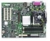
Server Board Connector and Component Locations, Server Board Components - s875wp1lx server board
 |
UPC - 735858161381
View all Intel S875WP1 manuals
Add to My Manuals
Save this manual to your list of manuals |
Page 11 highlights
Server Board Connector and Component Locations AB C D E FG CC H BB I AA J K Z L Y M X N W V O U P T A. System Fan 4 Header S R. Battery RQ TP00182 B. +12V CPU Power Connector C. Processor Socket D. CPU Fan E. DIMM Sockets F. Main Power Connector G. Floppy Drive Connector H. Auxiliary Power Connector I. Primary IDE Connector J. Secondary IDE Connector K. Serial B Header L. System Fan 1 Header M. System Fan 2 Header N. Front Panel Connector O. BIOS Configuration Jumper (J8J2) P. SCSI LED Header S. SATA-A1 through SATA-A4 Connector (S875WP1LX only, from left to right: SATA-A4, SATA-A2, SATA-A3, SATA-A1) T. Chassis Intrusion Header U. PCI 32/33 Slots 1 - 3 (slots numbered from top to bottom) V. System Fan 3 Header W. Front Panel USB Header X. Clear CMOS Jumper J8G1 Y. SATA-B1 and SATA-B2 Connectors (slots numbered from left to right) Z. AGP Connector AA. NIC2 (10/100 Mb) BB. NIC1 (1 Gb) CC. Back Panel I/O Ports Q. Hot Swap Backplane Header Figure 1. Server Board Components Server Board Features 11
-
 1
1 -
2
-
3
-
4
-
5
-
 6
6 -
 7
7 -
 8
8 -
 9
9 -
 10
10 -
 11
11 -
 12
12 -
 13
13 -
 14
14 -
 15
15 -
 16
16 -
17
-
18
-
19
-
20
-
21
-
22
-
23
-
24
-
25
-
26
-
27
-
28
-
29
-
30
-
31
-
32
-
33
-
34
-
35
-
36
-
37
-
38
-
39
-
40
-
41
-
42
-
43
-
44
-
45
-
46
-
47
-
48
-
49
-
50
-
51
-
52
-
53
-
54
-
55
-
56
-
57
-
58
-
59
-
60
-
61
-
62
-
63
-
64
-
65
-
66
-
67
-
68
-
69
-
70
-
71
-
72
-
73
-
74
-
75
-
76
-
77
-
78
-
79
-
80
-
81
-
82
-
83
-
84
-
85
-
86
-
87
-
88
-
89
-
90
-
91
-
92
-
93
-
94
-
95
-
96
-
97
-
98
-
99
-
100
-
101
-
102
-
103
-
104
-
105
-
106
-
107
-
108
-
109
-
110
-
111
-
112
 |
 |
