Intel S875WP1 Product Guide - Page 18
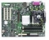
Serial Port, Parallel Port, Floppy Drive Controller, Keyboard and Mouse Connectors - e front panel
 |
UPC - 735858161381
View all Intel S875WP1 manuals
Add to My Manuals
Save this manual to your list of manuals |
Page 18 highlights
Serial Port The server board S875WP1-E has one serial port connector and one serial port header. The serial port A connector is located on the back panel. The serial ports' NS16C550-compatible UART supports data transfers at speeds up to 115.2 kb/s with BIOS support. A DH10 10-pin serial header is available on the baseboard for an option Serial B port. Parallel Port The 25-pin D-Sub parallel port connector is located on the back panel. In the BIOS Setup program, the parallel port can be set to the following modes: • Output only (PC AT*-compatible mode) • Bi-directional (PS/2 compatible) • EPP • ECP Floppy Drive Controller The I/O controller supports one diskette drive that is compatible with the 82077 diskette drive controller and supports both PC-AT and PS/2 modes. Keyboard and Mouse Connectors PS/2 keyboard and mouse connectors are located on the back panel. The +5 V lines to these connectors are protected with a PolySwitch* circuit that, like a self-healing fuse, reestablishes the connection after an overcurrent condition is removed. ✏ NOTE The keyboard is supported in the bottom PS/2 connector and the mouse is supported in the top PS/2 connector. Power to the computer should be turned off before a keyboard or mouse is connected or disconnected. The keyboard controller contains the AMI keyboard and mouse controller code, provides the keyboard and mouse control functions, and supports password protection for power-on/reset. A power-on/reset password can be specified in the BIOS Setup program. 18 Intel Server Board S875WP1-E Product Guide
-
 1
1 -
2
-
3
-
4
-
5
-
6
-
7
-
8
-
9
-
10
-
11
-
12
-
 13
13 -
 14
14 -
 15
15 -
 16
16 -
 17
17 -
 18
18 -
 19
19 -
 20
20 -
 21
21 -
 22
22 -
 23
23 -
24
-
25
-
26
-
27
-
28
-
29
-
30
-
31
-
32
-
33
-
34
-
35
-
36
-
37
-
38
-
39
-
40
-
41
-
42
-
43
-
44
-
45
-
46
-
47
-
48
-
49
-
50
-
51
-
52
-
53
-
54
-
55
-
56
-
57
-
58
-
59
-
60
-
61
-
62
-
63
-
64
-
65
-
66
-
67
-
68
-
69
-
70
-
71
-
72
-
73
-
74
-
75
-
76
-
77
-
78
-
79
-
80
-
81
-
82
-
83
-
84
-
85
-
86
-
87
-
88
-
89
-
90
-
91
-
92
-
93
-
94
-
95
-
96
-
97
-
98
-
99
-
100
-
101
-
102
-
103
-
104
-
105
-
106
-
107
-
108
-
109
-
110
-
111
-
112
 |
 |
