Intel S875WP1 Product Guide - Page 7

s, Tables, Connecting the Processor Fan Cable to the Processor Fan Connector - bios

Page 7 highlights

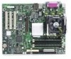
Figures Figure 1. Server Board Components 11 Figure 2. Back Panel Connectors 12 Figure 3. Front Panel Connectors 12 Figure 4. Location of the Standby Power Indicator LED CR7J1 29 Figure 5. Location of Clear CMOS Jumper 32 Figure 6. Installing the I/O Shield 41 Figure 7. Installing Chassis Standoffs in the SC5200 Chassis 42 Figure 8. Installing Chassis Standoffs in the SC5250-E Chassis 43 Figure 9. Placing the Server Board into the Chassis 44 Figure 10. Attaching the Server Board 45 Figure 11. Installing the Processor in the Processor Socket 45 Figure 12. Attaching the Heat Sink to the Processor 46 Figure 13. Attaching the Fan Heat Sink Clips to the Processor Socket 47 Figure 14. Attaching the Fan Heat Sink Clips to the Processor Socket 47 Figure 15. Connecting the Processor Fan Cable to the Processor Fan Connector 48 Figure 16. DIMM Socket Locations 50 Figure 17. Installing the AGP Card 52 Figure 18. Connecting the IDE Cable 53 Figure 19. Connecting the SATA Cable 54 Figure 20. Location of Internal Headers 55 Figure 21. Location of the Fan Headers and Power Connectors 57 Figure 22. BIOS Configuration Jumper Block Location 58 Figure 23. Removing the Battery 62 Figure 24. Power, Fan, and Chassis Intrusion Connectors 102 Figure 25. Add-in Board and Peripheral Interface Connectors 103 Tables Table 1. Table 2. Table 3. Table 4. Table 5. Table 6. Table 7. Table 8. Table 9. Table 10. Table 11. Table 12. Table 13. Table 14. Table 15. Table 16. Table 17. Table 18. Table 19. Table 20. Server Board Features 9 Supported Processors 13 Video Modes 16 PCI Bus Characteristics 20 PCI Bus Configuration IDs 21 10/100 Ethernet LAN Connector LEDs 23 10/100/1000 Gigabit Ethernet LAN Connector LEDs 24 Effects of Pressing the Power Switch under ACPI 25 Wake-up Devices and Events 26 Fan Connector Function/Operation 28 Supervisor and User Password Functions 31 Front Panel Header (J7J1 55 USB 2.0 Header (J7E1 56 Jumper Settings for the BIOS Setup Program Modes (J8J2 59 BIOS Setup Program Menu Bar 68 BIOS Setup Program Function Keys 69 Maintenance Menu 69 Main Menu...70 Advanced Menu 71 PCI Configuration Submenu 72 Contents vii

  • 1
  • 2
  • 3
  • 4
  • 5
  • 6
  • 7
  • 8
  • 9
  • 10
  • 11
  • 12
  • 13
  • 14
  • 15
  • 16
  • 17
  • 18
  • 19
  • 20
  • 21
  • 22
  • 23
  • 24
  • 25
  • 26
  • 27
  • 28
  • 29
  • 30
  • 31
  • 32
  • 33
  • 34
  • 35
  • 36
  • 37
  • 38
  • 39
  • 40
  • 41
  • 42
  • 43
  • 44
  • 45
  • 46
  • 47
  • 48
  • 49
  • 50
  • 51
  • 52
  • 53
  • 54
  • 55
  • 56
  • 57
  • 58
  • 59
  • 60
  • 61
  • 62
  • 63
  • 64
  • 65
  • 66
  • 67
  • 68
  • 69
  • 70
  • 71
  • 72
  • 73
  • 74
  • 75
  • 76
  • 77
  • 78
  • 79
  • 80
  • 81
  • 82
  • 83
  • 84
  • 85
  • 86
  • 87
  • 88
  • 89
  • 90
  • 91
  • 92
  • 93
  • 94
  • 95
  • 96
  • 97
  • 98
  • 99
  • 100
  • 101
  • 102
  • 103
  • 104
  • 105
  • 106
  • 107
  • 108
  • 109
  • 110
  • 111
  • 112

Contents
vii
Figures
Figure 1. Server Board Components
..........................................................................................
11
Figure 2. Back Panel Connectors
...............................................................................................
12
Figure 3. Front Panel Connectors
...............................................................................................
12
Figure 4. Location of the Standby Power Indicator LED CR7J1
.................................................
29
Figure 5. Location of Clear CMOS Jumper
.................................................................................
32
Figure 6. Installing the I/O Shield
................................................................................................
41
Figure 7. Installing Chassis Standoffs in the SC5200 Chassis
...................................................
42
Figure 8. Installing Chassis Standoffs in the SC5250-E Chassis
...............................................
43
Figure 9. Placing the Server Board into the Chassis
..................................................................
44
Figure 10. Attaching the Server Board
........................................................................................
45
Figure 11. Installing the Processor in the Processor Socket
......................................................
45
Figure 12. Attaching the Heat Sink to the Processor
..................................................................
46
Figure 13. Attaching the Fan Heat Sink Clips to the Processor Socket
......................................
47
Figure 14. Attaching the Fan Heat Sink Clips to the Processor Socket
......................................
47
Figure 15. Connecting the Processor Fan Cable to the Processor Fan Connector
....................
48
Figure 16. DIMM Socket Locations
.............................................................................................
50
Figure 17. Installing the AGP Card
.............................................................................................
52
Figure 18. Connecting the IDE Cable
.........................................................................................
53
Figure 19. Connecting the SATA Cable
......................................................................................
54
Figure 20. Location of Internal Headers
......................................................................................
55
Figure 21. Location of the Fan Headers and Power Connectors
................................................
57
Figure 22. BIOS Configuration Jumper Block Location
..............................................................
58
Figure 23. Removing the Battery
................................................................................................
62
Figure 24
.
Power, Fan, and Chassis Intrusion Connectors
.......................................................
102
Figure 25. Add-in Board and Peripheral Interface Connectors
.................................................
103
Tables
Table 1.
Server Board Features
....................................................................................
9
Table 2.
Supported Processors
...................................................................................
13
Table 3.
Video Modes
..................................................................................................
16
Table 4.
PCI Bus Characteristics
.................................................................................
20
Table 5.
PCI Bus Configuration IDs
.............................................................................
21
Table 6.
10/100 Ethernet LAN Connector LEDs
..........................................................
23
Table 7.
10/100/1000 Gigabit Ethernet LAN Connector LEDs
....................................
24
Table 8.
Effects of Pressing the Power Switch under ACPI
........................................
25
Table 9.
Wake-up Devices and Events
.......................................................................
26
Table 10.
Fan Connector Function/Operation
...............................................................
28
Table 11.
Supervisor and User Password Functions
....................................................
31
Table 12.
Front Panel Header (J7J1)
............................................................................
55
Table 13.
USB 2.0 Header (J7E1)
.................................................................................
56
Table 14.
Jumper Settings for the BIOS Setup Program Modes (J8J2)
........................
59
Table 15.
BIOS Setup Program Menu Bar
....................................................................
68
Table 16.
BIOS Setup Program Function Keys
.............................................................
69
Table 17.
Maintenance Menu
........................................................................................
69
Table 18.
Main Menu
.....................................................................................................
70
Table 19.
Advanced Menu
.............................................................................................
71
Table 20.
PCI Configuration Submenu
..........................................................................
72