Intel S875WP1 Product Guide - Page 57
Connecting Hardware Control and Power Cables
 |
UPC - 735858161381
View all Intel S875WP1 manuals
Add to My Manuals
Save this manual to your list of manuals |
Page 57 highlights
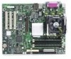
Connecting Hardware Control and Power Cables Figure 21 shows the location of the hardware control (fans and chassis intrusion) headers and power supply connectors. J1B1 A B J1F1 C 12 V I J7B1 H D E J6J3 F J6J2 G A. System Fan 4 Header B. CPU Fan C. Main Power Connector D. Auxiliary Power Connector E. System Fan 1 Header J9A1 TP00195 F. System Fan 2 Header G. Chassis Intrusion Header H. System Fan 3 Header I. +12V CPU Power Connector Figure 21. Location of the Fan Headers and Power Connectors Server Board Installation and Upgrades 57
-
 1
1 -
2
-
3
-
4
-
5
-
6
-
7
-
8
-
9
-
10
-
11
-
12
-
13
-
14
-
15
-
16
-
17
-
18
-
19
-
20
-
21
-
22
-
23
-
24
-
25
-
26
-
27
-
28
-
29
-
30
-
31
-
32
-
33
-
34
-
35
-
36
-
37
-
38
-
39
-
40
-
41
-
42
-
43
-
44
-
45
-
46
-
47
-
48
-
49
-
50
-
51
-
 52
52 -
 53
53 -
 54
54 -
 55
55 -
 56
56 -
 57
57 -
 58
58 -
 59
59 -
 60
60 -
 61
61 -
 62
62 -
63
-
64
-
65
-
66
-
67
-
68
-
69
-
70
-
71
-
72
-
73
-
74
-
75
-
76
-
77
-
78
-
79
-
80
-
81
-
82
-
83
-
84
-
85
-
86
-
87
-
88
-
89
-
90
-
91
-
92
-
93
-
94
-
95
-
96
-
97
-
98
-
99
-
100
-
101
-
102
-
103
-
104
-
105
-
106
-
107
-
108
-
109
-
110
-
111
-
112
 |
 |

Server Board Installation and Upgrades
57
Connecting Hardware Control and Power Cables
Figure 21 shows the location of the hardware control (fans and chassis intrusion) headers and
power supply connectors.
TP00195
A
B
C
E
H
I
12 V
F
J1B1
J6J3
J6J2
J7B1
J1F1
J9A1
G
D
A.
System Fan 4 Header
B.
CPU Fan
C.
Main Power Connector
D.
Auxiliary Power Connector
E.
System Fan 1 Header
F.
System Fan 2 Header
G. Chassis Intrusion Header
H.
System Fan 3 Header
I.
+12V CPU Power Connector
Figure 21. Location of the Fan Headers and Power Connectors